

Diagnose P2 Edge not loading programs
 macca
Posts: 1,079
macca
Posts: 1,079
Hello,
Sadly my P2 Edge module all of a sudden stopped working, or better, seems to work but doesn't allow to upload programs. I can't start the monitor nor taqoz. Seems that it doesn't receive any character. Tried different switch confiurations without any change.
Are there some easy checks I can do to at least try to understand what doesn't work ?
Something that can be done with very minimal tools like a multimeter and a (crappy) Bitscope micro ?
I don't think I'll ever be able to repair any damage with those tiny components, I'm just curious.
What worries me more is that since I don't know what caused the damage it could happen again.
So far I checked the prop-plug rx/tx with another prop-plug and both are sending and receiving correctly.
Checked the connection from the prop-plug connector on the carrier board with the pads on the back of the edge module.
Also checked the connection to P63 and P62 on the chip itself.
Checked the power 5v and 3.3v on the pin groups.
Checked the reset signal.
One thing I notice is that the leds on P56 and P57 doesn't light immediately at power on (not sure but I think they turned on immediately before), they take some seconds, then P57 light first, followed by P56. Don't know if this has some meaning. So seems that there is some activity.
I tried to wire an SD card in the attempt to boot from it but doesn't work, however I'm not sure to have wired it correctly nor that the boot file is correct.
I'm not sure if the flash has some programs on it, I was testing with a simple hello world sometime ago but probably it was overwritten with a program that does nothing.
Other informations:
P2-EC Rev. A (no PSRAM, nor micro-sd slot)
Edge module breadboard
Nothing connected other than the prop-plug
Comments
Ouch.
Suppose the one thing is that the power supply is bad? Can you measure the voltage supply to the edge module?
The usual killer of Prop 1/2 is too high a voltage on I/o pins. If there’s no way that happpened hard to imagine p2 edge module just suddenly dying…
I measured the voltage on the 5v pins, which, if I'm not wrong, come directly from the barrel jack on the breadboard, and it is 5.18.
The pins were not connected to anything with its own power supply, all devices (including the USB keyboard, that at the time was disconnected) are powered from the same source that powers the P2.
I can't think of anything too, especially considered that it was powered off working, and powered on few hours later not working!
Leading theory: Ṫ̉̎̒h̭̙̲̻͒ͫ̇ͤͅe̘̪̣͎͒̈́̈ͦ͠ ̢̼̔̈E̩̹̽̈̕ń̒̚҉̫t̵̔ï̠͇̺̜͇̯̻ͩ̏̋t̡̤̬̗̮̭͚̜ͧͦy came down on your abode at night and sucked all the yolk out of the chip. Really annoying. You can protect against this using a salt circle with the appropriate warding runes.
I think the LED behaviour depends on the different boot modes / their timeouts, but that's talking based on the EVAL, which has a lot more LEDs (the EC32MB has LEDs on 38/39 instead). Not at home right now, so can't check what it's supposed to be like. I guess you could check if the idle voltage levels on the boot-relevant pins actually match the intended boot mode.
Do remember the SD boot file needs to be called
_BOOT_P2.BIX(I keep forgetting the leading underscore)I had (non-Parallax) electronics brick before by being connected to a poorly-regulated 5V source over night, but if you had the power switch off, that shouldn't have done it.
Flexprop has a couple special modes that don’t depend on the crystal working. Might try that.
Usual things would be to unplug replug edge. Try different power supply if can.
If no way 5v or more made it onto p2 io pins, it’s pretty hard to kill…
Everything is in that small group of pins. If the comport ain't working then chances are neither will EEPROM/SD booting.
LED56/57 changing is nothing. Those are floating pins by default. The LED driver just follows wherever the floating goes.
Try the DIP switch for pull-up on P59 (#3 ON I think). This will force it to comport mode in case there is other pull-ups interfering.
The 3v3 and 1v8 supplies can be measured quite easily. But be very careful not to short them together with end of probe. There is a row of small ceramic capacitors along each side of the Prop2. The ends facing the Prop2 is the supply volts. The capacitors alternate. Every second one is 1v8, while every other is 3v3. Target the group at pins P56..P63.
That was my first theory also")
Yes, the file name is correct, it is just the compiled binary, right ? It doesn't require a special format or something ?
The power supply I'm using is quite strong (the label say 5v 4.0A, yes 4 ampere...) and was very stable with all the test I did with the USB devices and clock frequencies. I don't even remember where it comes from.
I see the options to set the clock frequency and mode but I guess is relative to the second-stage loader (of whatever it is using), I think that a normal reset put the P2 in whatever safe clock mode it can use, right ?
Tried to unplug and replug a number of times, tried to power from different USB bricks and also directly from the PC ports, differeent prop-plug, nothing changes.
No changes, I checked that the DIP switch worked as designed by measuring the pins voltage and seems good, the flash switch turns the pull-up on P61, the other switches the pull-up or pull-down on P59.
With the Bitscope micro I wasn't yet able to see if there is activity on flash/sd clock pin, either there is nothing (whcih means the P2 is broken) or the crappy scope doesn't sense anything...
At whcih frequency should the flash clock pulse ?
Measured the top row, looks good, alternate 1.8 and 3.3 volts.
As it is now, seems that the P2 core itself is dead.
@macca There is something here that doesn't need the crystal working to function...
@macca If it died just sitting there seems you have a legitimate right to free replacement? Ken would probably tell you to email customer support...
Yes... monitor, taqoz... I have the same on my IDE, they don't work.
I think it is well ouf of warranty, purchased quite some time ago (2021 possibly ?), used very much...
Suppose it’s possible for the reset circuit to get broken …. But that seems unlikely just sitting there…
@macca
I can get a replacement board over to you. Will aim to ship it out Tuesday.
Would you prefer P2-EC or P2-EC32MB ?
Did you check the breakout board/anything that the P2-EC is inserted into? I had exactly this problem. P2-EC32 worked, but couldn't be programmed via PropPlug. Both Propeller Tool and Flexprop didn't see the P2 on the serial port.
The problem was dirty contact on the edge connector. The reset signal did not reach the chip.
I was planning to purchase the P2-EC32MB from Mouser this week, I see they have some in stock.
So yes, if you can send me the P2-EC32MB would be great, thank you very much!
No problem... On the way !
Thank you for all the recent Spin Tools updates.
I tried the continuity between the prop-plug pins on the breadboard and the pads on the back of the Edge module and also to the P2 pins, all seems good.
The RESn pin has the protection diode so I'm not sure, the diode measure returns 0.5something, not sure it is correct. I tried to probe the voltage on the RESn pin and is 3.2v, when I push the reset button on the breadboard it turns to ~0.5 (don't remember the exact value), I think the reset is good.
Today I tried to probe the flash CS and CLK pins with the Bitscope micro to see if there is some activity, the CS pin stay high all time and never goes low, looks like the core never attempts to load a program from flash.
Could have been some variation of this:
https://forums.parallax.com/discussion/176149/when-p1-loads-but-will-not-function#latest
We destroyed 5 P1s before we figured out what was doing it...
Ouch... few resets because I touched a pin or two (or maybe the prop-plug pins) happened over time, can't remember if that day happened or not, but a static discharge is the only cause I can think of (winter clothes prone to electrostatically charging, in my case).
And now I'm afraid to even touch the reset button...
Another thing: If neither the power supply you have on the P2 nor the PC has a (properly connected - check it!) ground pin, the whole system will have a floating ground at ~120V, which can also cause interesting issues. This gets increasingly bad (more available current) the more such power supplies are sharing the same ground.
@Macca
Ouch indeed, those were some fat sparks! (And unproductive day or so...)
@Wuerful_21
Yes, they are both proudly properly grounded at DC or 60 HZ.. At the crazy fast Dv/Dt of a static spark though, not so much.... Talk about ground bounce!
This probably also explains the high mortality rate we had for SEGGER PROs in some really old fixtures before we started using the SEGGER Hub with Minis.
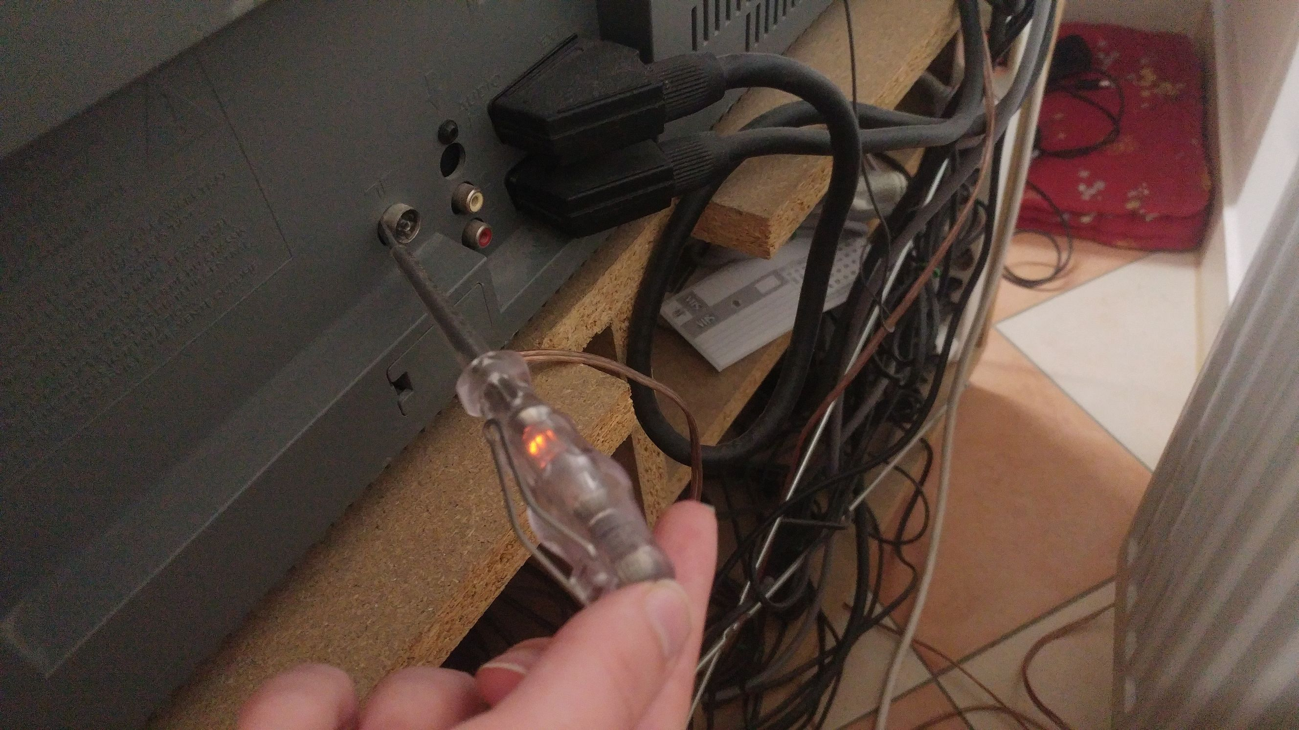
So, I tried those measurements as done in the video, and I can only conclude that the person in the video is sitting in close proximity to a fluorescent light or something else that is inducing 97 or so volts between the laptop and his body. This was the only way I could get the voltage checker screwdriver (Possibly the very same model in the video) to light, and get similar voltage readings between myself and nearby objects.
In the lab, I have only Dell laptops available, and all of the Dell power supplies I tested do not ground the shell of the connector although having grounding mains cables. This making my only ground for the laptop to be the Vss pin on the Prop Plug!
At the high Dv/Dt of the spark to the chassis, the inductance to mains ground can be quite a high impedance, and the capacitance to ground of the laptop can be quite a low impedance making the Prop Plug a significant route for the discharge current!
The power supplies in the fixture are also 'floating' (As most are...), but the chassis is carefully grounded to the incoming, and at least here in the lab, can be relied on to be truly grounded.
Up until now, I considered the programming/debug type ports to be special cases, use only under controlled circumstances. Well, the control is overrated, and these get hardened like any other external connection from now on...
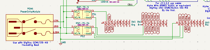
Just requires the right kind of dubious power supply. Witness, my TV (and associated 90s/2000s home theater rat's nest):
Phone charger also works, but the light is far more dim:
AKA, "Double Insulated".
In USA type setups, where the roadside 110 VAC supply is from many small centre-tapped single-phase transformers (I think), it floats to Earth potential. But most other parts of the world, where the AC supply is a Phase+Neutral from a larger shared 3-phase transformer, it instead floats to 50% of the house's AC supply volts.
EDIT: I'm unsure about the USA system to be honest. I suspect there is two options depending on whether 220 VAC is desired or not.
From hearsay I think many places do have the 2-phase 220VAC setup for large appliances, so the regular mains is also Phase+Neutral . I heard one time using two 50VAC phases to form the 100VAC mains is somewhat common in Japan? Either way, you can be sure some jackass somewhere is wiring a polarized NEMA socket to a dual-phase supply as we speak.
Only thing I know about Japan is their base 3-phase is 200 V between phases. Lots of Japanese equipment comes with 200 V 3-phase induction motors.
If they use the system of shared 3-phase transformer then that could make their single phase solution 115 VAC to Neutral. Of course, that also could apply to USA as well. Maybe both countries have optional choices of supply config.
Typical houses in the US are fed by a 240V center-tapped transformer, giving each house two 120V legs with opposite phases and a common neutral, or 240V across both legs. In the breaker panel, every other row of normal 120V circuit breakers connects to one or the other leg; 240V breakers span two rows to get both legs. The neutral and ground are connected at the main breaker panel and go to a ground stake, the plumbing system, and secondary and primary side neutrals of the transformer. The other side of the primary is fed by one of the three high-voltage phases from the substation. Groups of up to two or three houses and maybe a few street lights can share a single transformer.
I've only heard of weird ground things happening if the neutral connection to the pole fails, in which in the worst case, half of the equipment in the house can get blown up
I've not heard of houses only getting a single 120V leg, but maybe it happens in rural places that haven't been updated in a long time.
Thanks Electrodude, very detailed. Looks like I need to revise my ideas.
PS: A single leg wasn't what I had imagined either. It was both legs combined for 110 VAC with each at 55 V to the stake, no neutral to the house. I didn't even know the exact 120 VAC either. I was convinced it was 110 VAC. Maybe that is Japan like Ada said.
You are correct, on all counts.
Usually, US Residential is fed from a 220V center tapped secondary with the CT (Neutral) grounded. It can be from one phase of a 208/120 3 phase 'Y' setup with center grounded. It is a VERY old and rare house electrical service that has only 120V.
I have encountered 220 on the 120V polarized socket. I've encountered houses wired with 'zip' cord...
I hope there is a special place in hell for those house flippers/landlords that 'upgrade' the old ungrounded outlets by installing grounded outlets with the ground pin shorted to neutral. They WILL kill someone eventually. Probably already have... should go to JAIL at least.