

P2 based Pick and Place for P2
 Rayman
Posts: 16,461
Rayman
Posts: 16,461
Finally made some progress on this project...
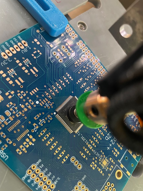
Can now pick up P2 translate and rotate to pads on PCB and finally place in perfect position.
Background: For assembling PCBs, I have a manual pick and place machine that is fine, except for big chips, like P2. It's very hard to get it just right. Maybe 25 % of the time it goes perfectly and no rework is needed. But, all too often, the P2 pins smudge the paste around and sometimes A LOT of rework is needed to clean up the P2 pins.
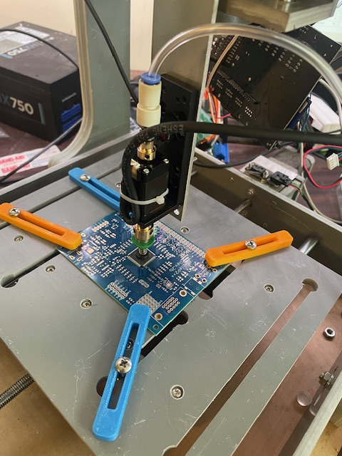
With this setup, can use modified CNC with a Juki pick and place head to place P2 perfectly every time.
For now, using Universal G-Code Sender to manually jog the P2 into place and then turning off vacuum pump to release.
As soon as find a 24 V supply and a switch, can use the Juki solenoid valve to turn off vacuum and release the P2.
This is looking to make my boards much cleaner looking and more problem free.
Here are photos of it during first test and pdf notes on how it was done...

Comments
Have to thank @mwroberts for the P2 code that talks to Universal G-Code sender from here:
https://forums.parallax.com/discussion/173389/p2-grbl-emulator-g-code-motion-controller-and-stepper-pulse-generator
Last year, used this setup to paint eggs. Might need to revert back to that soon (If can still buy eggs in April that is..)
https://forums.parallax.com/discussion/175775/cnc-egg-cookie-painting-bot
Plan to go forward with this is to use an actual CNC to machine an aluminum tray to hold P2 PCB in a fixed position and then hollow out a square hole on same tray for the P2 to sit in.
Thinking this will allow for a fixed G-Gode program to get the P2 and move into position.
Don't know if this setup can be rigged to automatically control the vacuum valve or not. Have to check into that. Maybe not necessary at first though because want to inspect P2 position above pads before lowering it into the paste...
The Juki hollow stepper includes a rotation sensor. Don't think going to need that for this, but might hook it up one day anyway...
Sorta working!
https://www.youtube.com/shorts/qKmXsRdGxLk
Next, want to see if any of these heads can pick and place 0402 parts...
So you are solving/avoiding needing any rotation sense and correction, but first manually placing the p2 into a cavity ?
The better P&P machines have a camera that checks the actual X.Y.R errors of the part when on the head, and then the final path corrects for those offsets.
Most trays and tapes have quite a bit of wobble so you may need that correction ability for smaller parts ?
@jmg Mostly right on all counts! But, the first P2 pocket was too loose and it did need 4-axis tweaking to get it right...
Today, made tighter pocket inside the loose pocket and now appears that no adjustment is necessary at all. This is great news.
Cheating on the P2 as much as possible now with just 2 axis movement needed, as this is main goal.
But, other parts, like 0402 caps will need 4-axis movement. If that doesn't work out, still have manual pick and place, so not a big deal.
Bought cameras and tested them for this. But, finding my near vision gives me microscopic vision super power when glasses are removed.
This gives a much better view than these cameras...
Anybody know what decides the speed of a desktop CNC?
If going to buy a new one (this one comes from a time before you could buy 3D printers), want it to be much faster...
This one was supposed to be for 3D printing, so maybe that's why it's slow?
Is it the motors or the motor drivers?
Or, maybe it's the drive? This one is direct screw drive. Maybe that's as fast as they get?
Think Shapeoko CNC at work has belt drive. Perhaps that gives a mechanical advantage...
Pick and Place an 0402 cap works!
https://www.youtube.com/shorts/jKiqFY2wUWQ
Starting to think this might work out. As long as not in a hurry...
One problem was that the tape was very curved because was from inner part of a roll. But, some double sided tape fixed that...
Here's the GCode that ran in the video:
Precise for sure.
Often pick machines will blow a little bit of air out the nozzle after releasing the vacuum, to ensure the part stays on the board. Just not too much, or the part could be blown across your PCB :-)
Paste contact helps to some extent too, and also reduces the risk of blown away parts, but you can't always 100% rely on a good paste contact at that moment of release.
Ohhh, yes that's really slow. If I do prototypes I place all parts manually. With tweezers and a bit of practice you can do around 1 part every 3 or 4 seconds. Only the fine pitch ICs need special attention. For manual placement I have a vacuum nozzle mounted on a passive vertical linear bearing. I pick up the IC, slide the nozzle to the up posiition. Then I place the PCB below the IC and carefully lower the nozzle until the pins of the IC are just ~0.5mm above the pads. Then I move the PCB in the XY plane and rotate it until all pins are perfectly aligned. You may need a camera or a magnifying glass lens and look exactly vertically to avoid parallax errors. Then lower the nozzle until the IC touches the paste on the pads and switch off the vacuum.
Just for fun and comparison, here is my current commercial P&P machine: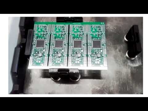
And this was my first DIY built with belt drives:
Just read that the motor voltage has a lot to do with how fast it can go with a load...
This ancient Makerbot motor driver is rigged for 12V. But, looks like it could all work at 24V. That would probably help a lot.
This setup uses ATX power supply for the 12V. From an ancient time before solid state power adapters...
No 24V here... Also, motor drivers have analog setting inputs. Think should scrap all the controls and buy new stepper motor controllers and a power supply...
But first, want to see what this can do...
@ManAtWork Thanks for the videos! Yes, that is like light speed compared to mine...
I'd love to have one of those. Nowhere to put it though at the house...
Unless you need to do high volume mass production top speed is not really that important. But a CNC mill is definitely too slow. 10s per part is OK but if it's much slower you're faster manually. A 3D printer should be suitable.
But remember, P&P technology means feeder technology. The 3D kinematics is the easier part. For blister tapes you need to remove the cover tape and advance the pocket tape. I like the "plow" aproach where only one side of the cover is removed and then lifted to the side exposing the pocket. To advance the tape you could build a ratched mechanism driven by a model servo.
@ManAtWork Agree with you that manual is faster for much of this.
My main goal here was to place P2 and that has gone well.
But, there are a lot of 0402 1uF on some of my boards. If those could be placed automagically, would be great.
The feeder is a problem. I'm attempting to solve it by using a strip of tape held in a fixed position using a slot and double sided tape.
The distance between caps should be constant? Also, strip should be aligned with x axis. Hoping some simple math will make this work...
Looks like M03 and M05 are used to turn a spindle on and off.
Think will use this to control vacuum pump.
Looks easy to add to the P2 GRBL code:
"m" : mvalue := DecIn(1,inPTR) 'G code command 'term.fstr1(string("G type: %d \r"),gvalue[buff_head]) new_move := 1 case mvalue 03 : pinh(53) 05 : pinl(53)Think just figured out that these solenoid valves require air pressure to operate as they are meant for pressurized gas...
Was naively (apparently) thinking they would work with vacuum as well...
Found something that should work, but guess need 2 of them:
https://www.amazon.com/gp/product/B07QRTF9ZQ/?th=1
Hi,
perhaps a few comments from a non-professional lower cost view:
The first question is, what you really want to do with the mechanics. If you really want to to mill, then the speed as is is not so bad, because stiffness and force are high in this setup and very important for precision. Probably your working spindle is limited in speed and power so you have to go slowly. Stiffness of the machine will limit things here too. It is all about finding the right compromise for the specific task. At my lathe force of the drive is critical because friction and work force do vary a great unknown deal.
Important question: What resolution do you really need? I would go for one full step per resolution step, because microsteps have lower stiffness. They are not very useful to give resolution. For a real non pro mill around 0,02mm/full-step resolution would be a good compromise, I think. The pick and place machine does not need very high stiffness, so here you could probably use 0,02mm/quarter-step. I have no experience there.
As you wrote high supply voltageis interesting. Here is the limit for a non professional machine, what voltage is considered harmless: DC 42V. A second problem is, that with higher voltage and current your drivers need better active cooling. So if you want to have it low noise, there is a trade off. Low cost driver modules are limited in voltage.
On the motor side the steppers are very different with the same housing. You want high torque but low back-emf (which defines the need for high voltage) and low inductivity. The problem with motors is that types with lower production volume are very much more expensive. Ideal would be long motors with integrated angle feedback. My knitting machine uses low cost motors NEMA17, length 48mm, 2A, R=1,4Ohms, 0,55Nm, 1,8° per full-step.
Spindles give high stiffness. For a real mill, I think they are the right thing. With the same diameter they are sold with different number of threads, which gives different travel per revolution. In my knitting machine I have one spindle TR8 with 8mm travel per rev, it's called "lead". You could probably easily swap to such spindles in you existing machine. Check it! For D=8mm there are 1, 2, 4, 8mm lead types available. For the pick and place machine I would go for 8mm. For a mill 2 or 4mm and I would consider ball screw spindles, which give high precision and no backlash. There are some lower cost ball spindles available now. The other two spindles for the knitting machine are ball screw 1605 with 5mm/rev. These are very interesting, I think. 5mm/200full-steps=0,025mm resolution.
I you use belt-drive for a low stiffness application, then there are special motors with 0,9°/full-step, which might be interesting.
For low noise you want to use >=32 microsteps. This means that your controller and software must be able to generate the required frequency. Here I had two interesting findings: 1. TMC2209 step drivers do the microstep interpolation themselves. You only need to send the number of steps needed for the resolution. 2. P2 can also send the interpolation steps using smartpin hardware pulse output.
It would be interesting , if my knitting machine would be faster, so I spent a lot of time finding the limits of the existing hardware. Actually here the speed is limited by oscillations and resonance. If you have long axis and spindles of low diameter this can become predominant. I do not fully understand, why also on the massive ball screws the limit is similar. So in this case I went down (!) with supply voltage to 15V. Also it is attractive to have not too much force in case of collisions and to have low cooling requirements. The precision needed is about +/-0,1mm, which is low compared to a mill but non trivial as the work-room is large. 8mm lead with 200 full steps bring 8mm/200=0,04mm resolution. So that is not bad. With about 781full-steps/sec I can achieve about 30mm/sec. (Edited)
Have fun, Christof
https://www.youtube.com/@stephen_hawes
@dMajo That looks like a much better looking version of what I'm trying to do.
The feeders look especially nice. Looks like main unit is $2k and feeders are $500 for 5.
Think could also copy 2 or even 4 or 5 nozzle setup. See that a lot.
Kind of surprised that works without interfering with tall parts on the board.
Must be some kind of system where one places the shortest parts first...
Here's a similar one that comes with 9 feeders, also ~$2k
https://www.amazon.com/Position-Electric-OPENPNP-Desktop-Machine/dp/B0DPR6ZW5F?th=1
These are something that maybe I could find room for... Thinking about it...
Here's another one:
https://www.boarditto.com/pick-and-place
Looks like these people are designing their own feeders. Kind of surprised there's not some standard one...
These are all giving me ideas... Didn't see these actual desktop sized machines before...
The OpenPNP software is interesting. Guess that is what a lot of these small machines are based on:
https://openpnp.org/
Seems not just software... OpenPNP appears to have a hardware side too.
Definitely something to look into...
Also like the price of this one, mentioned at openpnp:
https://pandaplacerstore.com/products/pandaplacer-a1
$750 but you have to 3d print some things yourself, like the feeders...
I am closely following Stephen's project more than 4 years. In the meantime I've seen many other P&P and CNC but noone convinced me as this.
This is opensource project, based on OpenPnP software.
https://github.com/opulo-inc
https://github.com/sphawes
I've seen another briliant idea for automatic head exchange from a german guy which I am implementing together with a conveyor. For the latest I will use a similar transport&clamp solution, again ingenious and at the same time effective and cheap, which is familiar to me (from ATON and HORUS AOIs).
Anyone seen this openPnp machine? Could be another contender, though I’ve not seen any reviews. Uses “standard” feeders apparently.
PSE-3000 looks good. Price is decent. But, store is flimsy. Seems you have to email to order. Also, have a feeling will be shipping from China...
I'm still thinking this is a perfect application for P2. Looks like it uses some kind of ARM chip that is about the size of P2.
Broke down and bought the PandaPlacer.
Says coming Thursday.
But, just got a note from UPS that I owe them $458 in tariff and import fees.
Can that be right? Seems a bit excessive for something that costs $870...
That sounds like one of the SCAM emails that are going around. Be sure to check for the obvious signs.
Isn't this, how tariffs work?
Talked to UPS and it's real. Would have been no tariff if under $800 under rules today.
But, over $800 and originally from China gets a crazy tariff now...
And, coming from Canada adds some extra on top...