

Is there a Camera Sensor Algorithm that detects "Significant Deviation" ??
 Christof Eb.
Posts: 1,597
Christof Eb.
Posts: 1,597
Hi all,
my actual project knitting machine should work unattended for hours. Unfortunately it deals with soft material (yarn and fabric) which has variations in behaviour. So a method of handling might work very often but fail eventually. Also problems can occur at different places.
So I am dreaming, if there might be a camera sensor (or better algorithm), which can be triggered at certain points in time in a repeating process and will detect differences in pictures. It should learn somehow, what is a normal deviation and what is a non-tolerable deviation and in this case stop the machine.
Perhaps someone can give me some hints?
Thanks Christof
Comments
Well, if it's due to weak yarn then maybe add a tensioner early in the feeder so that the yarn breaks before it is used.
maybe some hints in these:
I would think you'd start around here
Canny Edge Detection
some of these may be too pattern oriented, but may come in more useful detecting quality of the knit
GLCM
GLCM
this might serve well, too
HOG
In your knitting scenario, I expect, you'd take a picture at the consistent points in the process to compare a picture of each succesive image of that same point, and there fore have the variation constrained to small portions of the whole image. I wonder if you need to get that clever at all. but, the HOG link is standing out to me, even for my own projects, with these features:
There are several key properties that make HOG well-suited for feature extraction in medical imaging:
Insensitive to geometric and photometric transformations — Medical images can vary significantly in terms of scale, rotation, illumination etc. HOG is invariant to these transformations, allowing robust feature extraction.
Captures edge/shape information — The histogram of gradients captures important shape and edge information in an image which can be useful for identifying anatomical structures.
Unsupervised feature extraction — HOG does not require any labeled data to extract features. This is important for medical imaging where labeled data is often scarce.
Noise tolerant — Due to the coarse regional sampling and normalization, HOG can handle noise in images quite well. Medical images frequently contain noise.
Simple and efficient to compute — The HOG algorithm is relatively simple to implement and efficient to compute making it very practical.
If you go the camera way, why not take a look at Pixy2 and OpenMV cameras. At least the newer OpenMV camera models are able to also run machine learning models, although your use case might not need ML.
Thank you for your inputs! Very much appreciated! Plenty to read, @refaQtor . @banjo I had had a very short look at these two, but I will look more closely. Sometimes I don't know the right words/terms to see or google.
@evanh The variation of the breaking load of the yarn is not the problem. Breaking of yarn was only a secondary failure. The minimum of the variance here is quite high; it is really hard to break this yarn by hand. Variation of bending stiffness and of friction are making more trouble. They lead to variations of the position of the slings. Which in turn can add up, that the needle does not find the sling.
But your input is good: The yarn should be the weakest point, as it can be easily replaced and also yarn breakage can be relatively easily detected.
Cool.
Any chance that latent heat, after a short radiation, might differ with the different makeup of the yarn? I'm assuming the stiffness and friction is due to variations in material makeup of the yarn.
There's also the possibility of improving the behaviour of the yarn by adjusting treatment. Rasing the ambient knitting temperature and adding moisture for example.
I don't understand this sentence. What do you mean with "short radiation"?
(The last failure which I don't understand at all, occurred around midnight but it was full moon then. Some knitters will be convinced, that the phase of the moon has influence....)
Yes temperature and moisture are factors to consider. Unfortunately my machine is partly built of wood, so some deflection might come from that side also. I have now turned off the automatic lowering of room temperature in the night. - All in all I hope that the process can be made sufficiently resilient to allow "usual" variations.
As in some directed heating, a radiant element, at the yarn as it feeds. The idea here is an IR sensor can provide a fast response simple amplitude of the fading temperature after having been heated. This may well vary with differing stiffness/texture of the yarn. It's a slightly wild idea.
Oh, I had seen another topic about that, it hadn't been something I was reading ... two of them:
https://forums.parallax.com/discussion/174934/p2-controls-circular-knitting-machine-for-2-color-jacquard-pattern/p1
https://forums.parallax.com/discussion/176024/super-liesl-a-p2-controlled-cnc-linear-knitting-loom/p1
I yesterday read about "Histogram of Oriented Gradients". Yes, this seems to be promising here, because in a picture the "deviations" to look for are deviations of direction of the yarn.
It's a pity that I don't have a good camera interface for P2. The HOG method should be applicable to be used with P2, because it reduces the amount of data very early in the processing. It's enough to hold 3 lines in RAM at a time. And I could spare a cog for it. Plenty of time to analyse the picture here. Unfortunately I have used the same pins now to interface the step motors. On the other hand, a HOG camera seems to be a bigger project in itself....
OpenMv seems perhaps to be a possibility to get this running faster. I have an ESP32Cam, but it is not good and it suffers badly from lack of free pins.
Funny, internet seems to become swamped by articles created by AI. So many resources about HOG just reiterate the same content. For example they all refer to 9 direction bins, without telling, why they don't use 8.
I have not yet found an article about reaction to a significant but unknown deviation. Must be a common problem: "Hey there must something wrong here."
there need only be 2 pins for UART between the ESP32 and the P2. cook up a simple message pattern between the two.... was the strategy I had been planning with my ESP32CAM boards (when I get to them)
you've gotten deeper already than me, but I think about it as a 3x3 grid - 8 directions around the edges, and 1 of the no-gradient case in the center. don't take that too literally, it is just how I'm holding these first thoughts in my head that might jog something in yours as you understand/apply it.
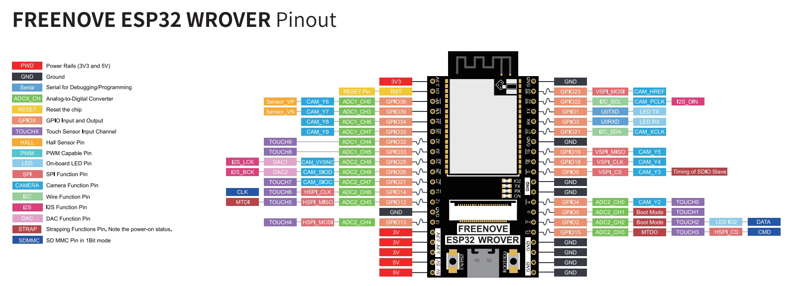
also notice, there is another version of the ESP32 setup for camera the WROVER that has an exposed RxTx https://www.amazon.com/FREENOVE-ESP32-WROVER-Compatible-Wireless-Detailed/dp/B0CJJHXD1W/
Yep, ordered such bigger WROVER board with camera and also with SD-card holder and USB-Serial. They seem to have GPIO32+33 free. And the message pattern shall be a Forth system....
This shows a good pattern:
So I got started with "Histogram of Oriented Gradients". I think this is very interesting, because it is a way to compress the information of a picture. It's running on the ESP32 Rover Camera. The picture is captured as QVGA 320x240 JPEG and stored on the SD-card, then converted to BMP.
From here I work with my "YAFFA-Forth" (Stuart Wood)
From BMP to 8bit greyscale. (2,3sec)
Histograms in 4 directions for 40x30 cells 4800 bytes. (14sec)
Get averages and normalise. (1sec)
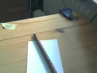
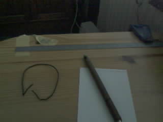
The original picture:
A ASCII greyscale representation, only every 4th pixel in a line printed and only every 8th line:
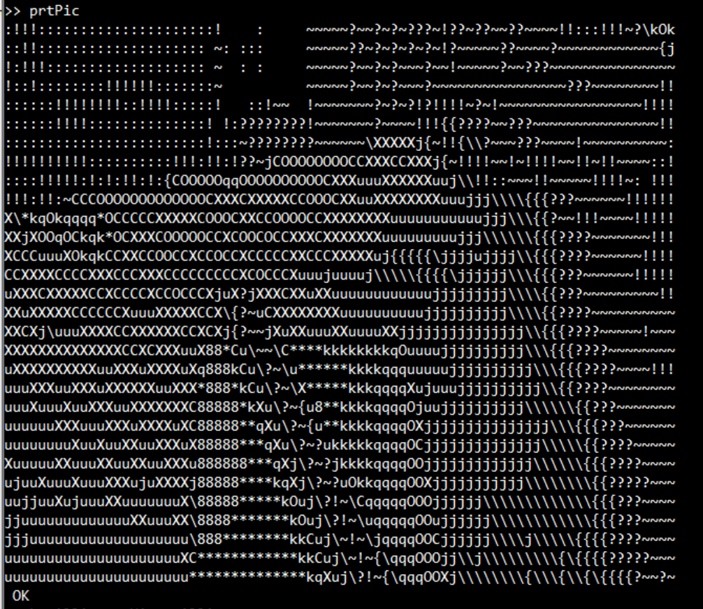
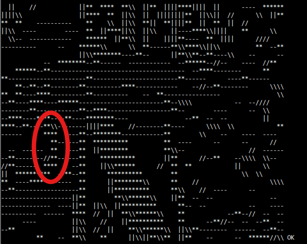
HOG representation for numbers > 160. The signes go parallel to lines. - is horizontal, * means several directions prominent. Before normalisation:
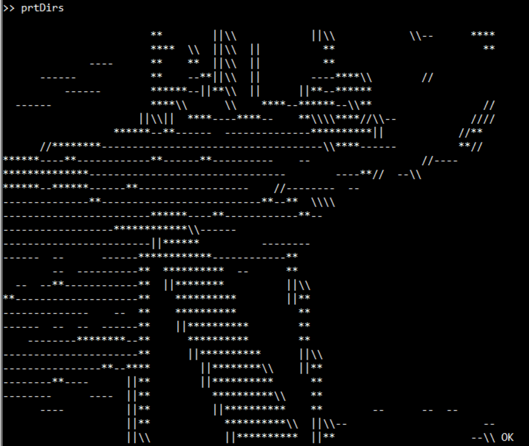
and after normalisation:
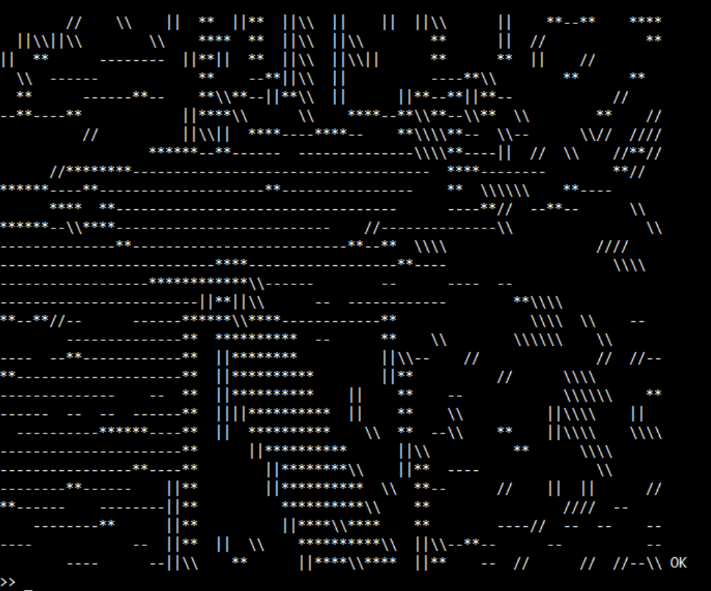
So the normalisation brings more information from the shadow. Generally shadows are very prominent.
Probably I will do the generation of the histograms in C, because here we have to handle the large number of pixels.
Have fun!
Christof
very cool @"Christof Eb."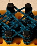
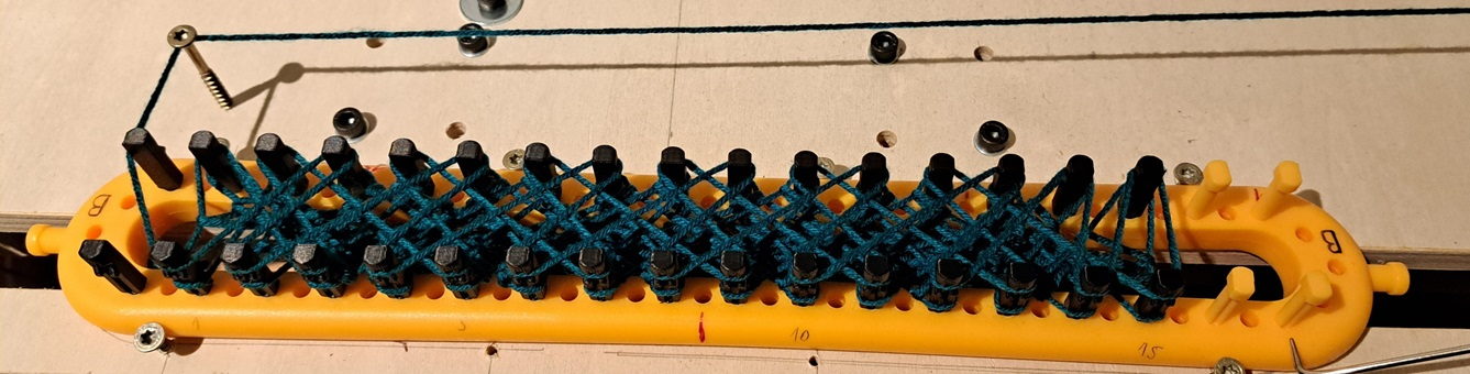
curious to see what it does with this:
I suspect getting up close and examining chunk chunk chunk at a time might give the necessary resolution for this effort with these low-res algo.
each square section of 4 pegs could be snapped from a camera, mounted on the tool head, at suitable points in the threading-on-the-next-row-of-yarn stage.
Hi,
I am a very beginner with this methods but I am thinking, that the lowering of resolution is not as bad in my case. The pictures only show a small part of the information in the histograms.
A thread has a diameter of >=1,4mm, so to be able to see it, we need a pixel diameter of 0,7mm. With a loom length of about 28cm, VGA with 640x480 should be enough to capture the whole loom in one shot. The camera can do that and more, though Freenove writes "We recommend that the resolution not exceed VGA(640x480).".
The algo swaps the information "at this pixel, we have a grey value of 145" to the information "in this 8x8 pixel region, there is some predominant structure in horizontal direction. And also some less important structure in \ - direction." So in this use case, the HOG form of information seems to be pretty interesting. - If you would want to read a barcode, where all information is in one direction, it will be completely useless. You can find a barcode in a picture, though.
The black wire of 1,6mm Diameter can be seen in QVGA of width of about 26cm.
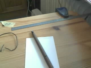
The Information that there is something with other directions than the wood structure is still there in HOG 40x30.
At the moment, I am just experimenting and learning....
Not sure if you're looking for a DIY or commercial solution, but when I worked in industrial control, I was asked to program a Keyence sensor to detect missing backboards and / or grommets from a vertical conveyor before the robot tried to pick up the product, which would usually result in product all over the floor. The Keyence sensors were programmed using a PC and software and taught to detect variations in the photos it would take to determine issues. It interfaced to a PLC via a very simple I/O interface and had a pretty good success rate at detecting missing grommets on the wickets, as well as whether a backboard was installed. Hard to explain without being able to show you the process, but other systems would fail because the grommets look just like the holes in the backboards to a camera. The Keyence software had the ability to use a high-contrast mode to help with this issue.
https://www.keyence.com/products/sensor/vision-sensor/
So I found another way to do the normalisation in this paper: https://www-users.cse.umn.edu/~hspark/csci5561_S2020/hw1.pdf It uses the average of squares. The paper is nice, because it tells you in detail, what you have to do.
The picture is rather dark, because it is evening now here. But not so much shadows.
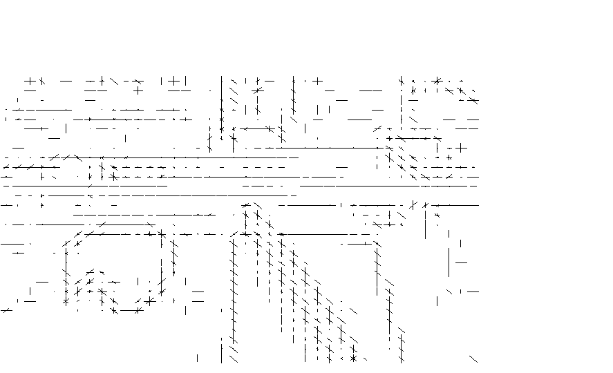
Also I now had an opportunity to use TEK4014 graphics, which is possible in Teraterm terminal emulation. The length of the lines gives the magnitudes.
Meanwhile I have realized, that in the paper mentioned above in #18, https://www-users.cse.umn.edu/~hspark/csci5561_S2020/hw1.pdf my original question is answered fully:

Pearson Correlation Coefficient can be used to compare two sets of data. (They call it NCC in the paper.)
https://en.wikipedia.org/wiki/Pearson_correlation_coefficient
It is interesting that, while in the paper mentioned in #18 the Correlation Coefficient is applied to the HOG matrices, you can also apply it directly to the grey values, as done in this paper: https://www.ipb.uni-bonn.de/html/teaching/photo12-2021/2021-pho1-09-matching-cc.pptx.pdf .
My first trials with HOG and a picture of the knitting loom are less encouraging. I think, I will have to go over to higher resolution and probably process only a part of a picture at a time. -Oh, you have been right, @refaQtor.- I think, that HOG can extract the direction of one single thin thread in a cell astonishingly well, but it cannot give good information if there are several threads in this cell.
Also like for human eyes, the dark blue yarn is difficult to see.
Thanks for pointing me at the Keyence products and their website, where they show, what can be done. - I am using this opportunity to learn "how picture analysis works" and see, what I can do with very low cost hardware.
For the fun of it: Can you spot the error?
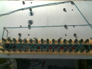
Still only QVGA, NCC applied to single HOG cells. Low numbers mean big difference. The light from the window is fading, so the lamps take over. I think this is responsible for the stray errors.
For simple things one can make templates of good and bad images and then use the sad algorithm to see which fits best…