

Need help with numbers...
 Theseus88
Posts: 6
Theseus88
Posts: 6
I need help converting ASCII to decimal. I built a little rover and I use two propeller chips. One runs the motors and the other will eventually monitor an IMU and proximity sensors. The two chips need to communicate though. I am using Dec and DecIn from the Parallax Serial Terminal.spin to send commands back and forth but I am having trouble... What could I do here... I have provided code...
Primary Controller Code:
PRI StartMotors(FrontLeftDuty, FrontRightDuty, BackLeftDuty, BackRightDuty, Frequency)

  repeat
    propeller.Dec(3)
    Command := propeller.DecIn
    if (Command == 1)
      quit
  repeat
    propeller.Dec(FrontLeftDuty)
    Command := propeller.DecIn
    if (Command == 1)
      quit
  repeat
    propeller.Dec(FrontRightDuty)
    Command := propeller.DecIn
    if (Command == 1)
      quit
  repeat
    propeller.Dec(BackLeftDuty)
    Command := propeller.DecIn
    if (Command == 1)
      quit
  repeat
    propeller.Dec(BackRightDuty)
    Command := propeller.DecIn
    if (Command == 1)
      quit
  repeat
    propeller.Dec(Frequency)
    Command := propeller.DecIn
    if (Command == 1)
      quit
Motor Controller Code:
PRI ListenForCommands | FrontLeftDuty, FrontRightDuty, BackLeftDuty, BackRightDuty, Frequency

  terminal.Str(String("Listening For Commands", terminal#NL))
  propeller.Clear
  repeat
    Command := propeller.DecIn
    terminal.Str(String("Command Received: "))
    case Command
          1 : terminal.Str(String("Are You There?", terminal#NL))
              propeller.Dec(1)
          2 : terminal.Str(String("Stop Motors", terminal#NL))
              propeller.Dec(1)
              StopMotors
          3 : terminal.Str(String("Start Motors", terminal#NL))
              propeller.Dec(1)
              FrontLeftDuty := propeller.DecIn
              propeller.Dec(1)
              FrontRightDuty := propeller.DecIn
              propeller.Dec(1)
              BackLeftDuty := propeller.DecIn
              propeller.Dec(1)
              BackRightDuty := propeller.DecIn
              propeller.Dec(1)
              Frequency := propeller.DecIn
              propeller.Dec(1)
              StartMotors(FrontLeftDuty, FrontRightDuty, BackLeftDuty, BackRightDuty, Frequency)
      other : propeller.Dec(-1)

Comments
Hi,
I don't use Spin, but I do think, that it is necessary to send a delimiting char after each number, that the receiving routine can know, that the number is now complete. A blank or CR or...
Christof
If you're receiving an ASCII character representing a number, such as "0", its value is $30 ($39 for "9"). If you're testing for or need a decimal value, you would first need to convert your ASCII values to decimal by subtracting $30 from the ASCII character value. Also, if you're only expecting a numeric value, I would limit it's range to 0-9 ($30-$39). I'm at work, so I didn't really give your code a thorough glance.
decin requires a cr terminated decimal string
PUB Decin : value
{{Receive carriage return terminated string of characters representing a decimal value.
  Returns: the corresponding decimal value.}}
dec sends a decimal string without cr.
So after every dec command add sending a cr (NL)
I appreciate the feedback, and I was able to figure it out. Now I am having trouble with the back motors PWM all of a sudden not working. In the following code I launch two cogs to control the four motors I have.
PRI StartMotors(FrontLeftDuty, FrontRightDuty, BackLeftDuty, BackRightDuty, Frequency) | Period, FrontDutyA, FrontDutyB, BackDutyA, BackDutyB

  StopMotors
  if (FrontLeftDuty > 0)
    outa[Front_AIN2]~~
  elseif (FrontLeftDuty < 0)
    outa[Front_AIN1]~~
    FrontLeftDuty *= -1
  if (FrontRightDuty > 0)
    outa[Front_BIN2]~~
  elseif (FrontRightDuty < 0)
    outa[Front_BIN1]~~
    FrontRightDuty *= -1
  if (BackLeftDuty > 0)
    outa[Back_AIN1]~~
  elseif (BackLeftDuty < 0)
    outa[Back_AIN2]~~
    BackLeftDuty *= -1
  if (BackRightDuty > 0)
    outa[Back_BIN1]~~
  elseif (BackRightDuty < 0)
    outa[Back_BIN2]~~
    BackRightDuty *= -1
  Period := clkfreq / Frequency
  FrontDutyA := -Period * FrontLeftDuty / 100
  FrontDutyB := -Period * FrontRightDuty / 100
  BackDutyA := -Period * BackLeftDuty / 100
  BackDutyB := -Period * BackRightDuty / 100
  FrontMotorsCog := cognew(RunMotors(Front_PWMA, FrontDutyA, Front_PWMB, FrontDutyB, Frequency), @FrontMotorsStack)
  BackMotorsCog := cognew(RunMotors(Back_PWMA, BackDutyA, Back_PWMB, BackDutyB, Frequency), @BackMotorsStack)
  outa[Front_STBY]~~
  outa[Back_STBY]~~

PRI RunMotors(PinPWMA, DutyA, PinPWMB, DutyB, Frequency) | Period, Time

  ctra[30..26] := ctrb[30..26] := %00100
  ctra[5..0] := PinPWMA
  ctrb[5..0] := PinPWMB
  frqa := frqb := 1
  dira[PinPWMA] := dira[PinPWMB] := 1
  Period := clkfreq / Frequency
  Time := cnt
  repeat
    phsa := DutyA
    phsb := DutyB
    waitcnt(Time += Period)
In my test code I tell the motors to drive forward, then stop, then turn, then stop, then go forward again and essentially repeat to drive in a square. When the code gets to the third iteration the back motors quit driving. I checked the voltages on the back motor driver I am using with the propeller and everything checks out except the PWM. For the first two iterations I can see the PWM go to 3.3V but on the third iteration it stops getting the PWM signal from the propeller. So I am assuming its something with how I am launching the cogs. Any advice would be great.
Heres the test code:
Personally, I never found the Parallax Serial Terminal object very useful except for simple projects -- something your code is not.
I wrote a parser engine so that I can send accept text-based commands from an external device (terminal, BT module, another processor, etc.). After a few updates I've attached my basic parser demo and then I made a simple demo that kind of matches what you're doing (on the robot end only). The way this parser works I'm able to test everything manually through PST (the terminal, not the object).
If I do say so myself, developing this way can be quite fun as you can create your own command language with no parameters, fixed parameters, or variable parameters. The demo shows all that.
Edit: See jm_tb6612_tester archive in post #12
TIP: Posting unformatted Spin is annoying to most other forum members because it renders your code unreadable. You can drag-select your code, select the Paragraph icon in the toolbar, then click on Code in the dropdown. Personally, I just add three backticks (unshifted tilde key on US keyboards) on the lines before and after my code.
Thanks Jon! Any ideas why the PWM on the second motor cog would just stop sending a signal with the code I do have? I was thinking about using FullDuplexSerial later just trying to work out how I want to command the motors still since I had never done PWM before now. Here is my basic circuit for the motor controller side of things:
And of course the rover...
Video of PWM Issue on YouTube
Well I changed the following code:
PRI StopMotors

  outa[Front_STBY]~
  outa[Back_STBY]~
  if (FrontMotorsCog >= 0)
    cogstop(FrontMotorsCog)
    FrontMotorsCog := -1
  if (BackMotorsCog >= 0)
    cogstop(BackMotorsCog)
    BackMotorsCog := -1
  outa[Front_AIN1]~
  outa[Front_AIN2]~
  outa[Front_PWMA]~
  outa[Front_BIN1]~
  outa[Front_BIN2]~
  outa[Front_PWMB]~
  outa[Back_AIN1]~
  outa[Back_AIN2]~
  outa[Back_PWMA]~
  outa[Back_BIN1]~
  outa[Back_BIN2]~
  outa[Back_PWMB]~
To this:
That seemed to fix the strange PWM issue I was having. Here is a short video of it working on YouTube.
Does it have to do with StartMotors() launching cogs that are not tracked, hence cannot be shutdown?
I posted my parser demos above -- sorry for the delay. I decided to add numeric support and ran into a hidden gotcha that delayed posting. It works now, though, and it understands numbers in the formats understood by Parallax tools: decimal, hexadecimal, and binary. What I enjoy about a parser like this is I can test using the terminal. When everything is working I route the serial command in from another device.
@Theseus88
Also in
StopMotors(), I don't know if you intended it originally, but "greater than or equal to" in spin1 is written like=>, not>=as you had in your original version (the more common syntax spin2 or most other languages use), so that might've been (part of) the issue.>=and<=are forms of assignment in spin1.Cheers,
Jesse
Good catch, Jessie!
@Theseus88
Long-term I think you'll want to break-up your program into smaller pieces. Given the utility of the TB6612 and you're using two of them, a stand-alone object seems reasonable. I couldn't sleep last night so I knocked one together after searching for anything available to the Schmarschmino community. The object loosely follows what I found from the SparkFun library except that it is setup to work with both drivers in the TB6612 (borrows from a 2-motor object I have used in JonyJib.com products). I did find a TB6612 object in ObEx, but it seems to require two cogs as the main object calls a separate PWM object that only uses one of the counters.
While looking though your code I notice that you are being very verbose about IO states. This is good -- except when a pin is going to be controlled by another cog.
Here's an example from your program -- you float the RX pins but set the TX pins to outputs.
You don't need to make the TX pins outputs in the master cog because the serial cog(s) will do that. In this case if you accidentally write a "1" to a TX pin in the master cog, the serial cog will always be putting out an idle state. Yeah, not likely to happen, but you don't know who might end up with your code and what mods they accidentally make.
Since I don't yet have driver boards or a robot (fixed that with a late-night Amazon order), I connected my LA to verify outputs. The attached test program uses my parsing engine. Maybe you could give this a try. I think you'll find it useful as the parsing engine allows you to create your own command language (I do this in a lot of projects which is why I wrote the parser object).
Update: Got the drivers and some cheap motors from Amazon. Found a bug in the driver that is now fixed. Here's a screencap of PST from the updated test program (v0.3.1).
Note that it has features for dealing with IO pins directly, as well as setting the motors -- I thought this might be useful for a robot.
Good luck with your project. In the latest version I added WS2812b pixel outputs.
I appreciate all of the feedback and help from everyone. The >= being switched to => seemed to resolve the strange pwm issue. This weekend I went out and got a Playstation 2 controller and then used a Propeller Mini I had laying around with another XBee to be able to control the rover from the PS2 controller wirelessly. I decided to use FullDuplexSerial and that seemed to solve the numbers issue I was having and instead of sending numbers as strings I made a simple parser using the FullDuplexSerial sort of like JohnnyMac suggested by having a parser. I feel like I definitely got a lot done in the past week. The Propeller 2 XBee Quick Bytes video also helped a lot with getting the XBee's into Transparent Mode. I have the IO4 on the rovers XBee set up to soon be connected to a NPN transistor to control a P-MOSFET that switches the high side power from everything else except the XBee (Remote Killswitch...). The XBee has its own little 3.3V regulator so its always powered. On the PS2 Controller's XBee I have it's IO4 setup to be connected to a toggle switch here later also. Question though... With the toggle switch should I have it connect to ground with a resistor or 3.3V with a resistor?
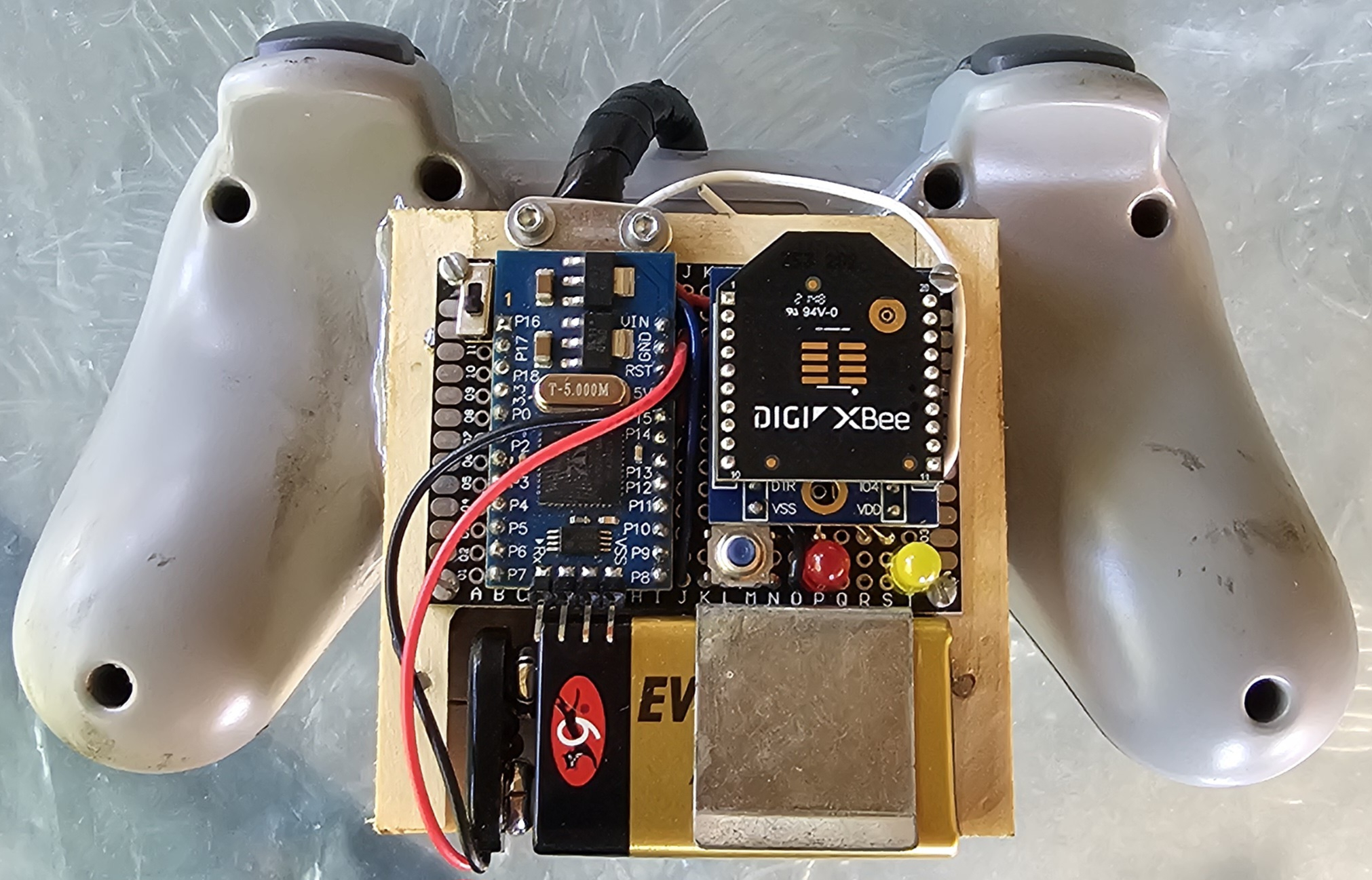
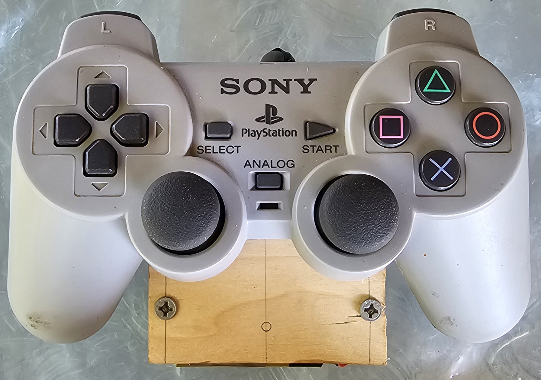
Also, I was super happy when I found the code for a Playstation 2 controller on the OBEX! Here is a picture of my controller:
Here is my code so far for all three Propellers. Any reviews would be great too! Again, I appreciate all the help above!!!
Neat.
Remember, you don't want to set an IO pin to output state when it will be controlled by another cog. This is from your main program
You have a similar situation in the rover program with TX and PWM pins.
Are you using your XBees in pass-through mode? In my laser-tag job we use XBees so that the guns can be started and stopped by a remote control program; this also lets them send scoring messages. In our case we use API1 mode.
Just started looking through your remote code. Again, same problem with setting TX pins to outputs (the serial cog will do that).
If I wasn't clear in the video you watched, the odd baud rate only applies to Series 1 radios. The baud rate generator in Series 3 radios is much better and you can use standard values.