

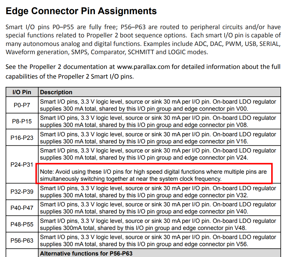
P2 Edge warning note regarding pairs of high-speed digital signals on P24-P31
 ngeneer
Posts: 62
ngeneer
Posts: 62
in Propeller 2
Can I get a little more clarification on the issue with these pins?
I had designs where these pins would be configured for either 4 pairs of UART RxTx (not SPI or I2C) or open for end user configuration. I want to know what limits I'd have on Baud rates or configuration limits or messages for the end user of these pins.
Comments
It's due to the built-in crystal oscillator circuit picking up the switching noise (It's missing a Schmitt trigger on XI pin input buffer) from the common power rail of pins P28-P31 inside the Prop2. The reason P24-P27 are included is because on the Eval Boards and Edge Cards they are joined external to a common power rail also.
Rule of thumb is don't use the default FAST pin drive on those pins. Any lower current setting, like DAC output, is fine.
PS: Actually, using an external CMOS buffered oscillator, leaving XO pin unconnected, solves it too. Then you can use FAST pin drive again.
EDIT: Crossed out power rail as the means. It has to be crosstalk instead.
As far as I remember, if you have one of the recent Revs of the Edge board, they use a CMOS osccillator and thus don't have this issue..
Yes, I think they changed to a HC2GU04 buffer so the P2 xtal oscillator is no longer used, which avoids injection jitter effects.
I think that was from a long time ago when there were also issues with the xtal wiring. Think that was the real problem.
Haven't noticed this issue on the SImpleP2 board where P30 and P31 are used at high speed for PSRAM clock with xtal input.
PCB does support CMOS oscillator instead, but haven't seen the need...
I mean there is that big issue where the PSRAM just doesn't work right in /2 clock mode.
I think it was @evanh that make a program to test for this issue and seems it was just the parallax boards that had it…
Although I recall only a couple non-Parallax boards being tested...
The cmos oscillator only costs a little more though. But I like my crystals for some reason…
There's no specific test in purely software. The side effect of the jitters is poor stability of post-PLL sysclock. How that impacts the operation of the Prop2 in use may not be obvious or even problematic at all.
Testing was simple though. Hook up a frequency meter or oscilloscope for monitoring a simulated clock output and start bashing the P28-P31 output pins - Alternating all on, all off. It should maintain a predictable and rock solid single frequency.
I usually start a smartpin set for sysclock/1000 for that clock. Then, say a 200 MHz sysclock, will read as 200.00 kHz on the meter.
PS: 200 MHz is sort of an ideal set frequency for sysclock, BTW. The PLL is naturally most stable around there.
It may have been me. I made a quick SPIN2 test routine to demonstrate the issue to Chip if a video driver was already running which clearly shows the P2 CPU jitter on screen.
https://forums.parallax.com/discussion/173205/how-to-kill-a-p2-video-driver-and-probably-usb-etc/p1
Thanks Roger. Good link, I'd long forgotten it. Chip's second post in there covers the bases well - https://forums.parallax.com/discussion/comment/1520712/#Comment_1520712
Huh, and I'd also confirmed differential drive also helped a lot. I'd forgotten that, and it's an intriguing find because it pretty much says the problem is not the power rail at all! https://forums.parallax.com/discussion/comment/1520811/#Comment_1520811
So I got that idea wrong above. It has to be a signal crosstalk problem I guess.
OK, I glean these relevant specifics for me:
from @cgracey
"If enough pins in the P28..P31 block are toggling fast at full strength, it can trigger this problem."
and further clarification from @evanh ..
"In fact, any two of those four pins is enough.
Interestingly, using OUTNOT instead of OUTRND I can refine it a little further.
There is no problem if driving two pins inverted from the other two. It can even be 28 and 29 one polarity with 30 and 31 the other polarity."
I see further documentation notes have been added deeper than I had needed to go.
thanks from the links and clarification!