Flight simulator, 3DOF motion rig
 ManAtWork
Posts: 2,283
I've already mentioned it in the "force feedback joystick" thread. Me and a friend are currently building a motion flight simulator.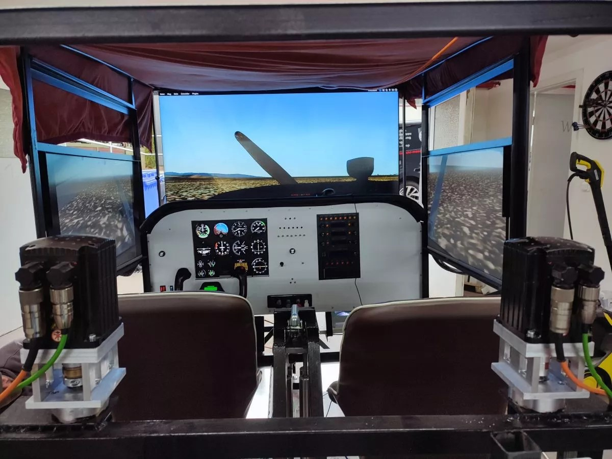
It is equipped with 3 servo motors I have left over from building my CNC machine. They have 1hp to 1kW and each drive a ball spindle with 20mm diameter and 10mm pitch. So we have 3 degrees of freedom (roll, pitch and lift).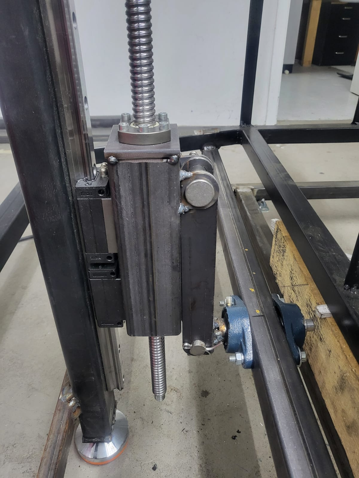
The motors are powered with 230VAC drivers controlled by a P1 each. 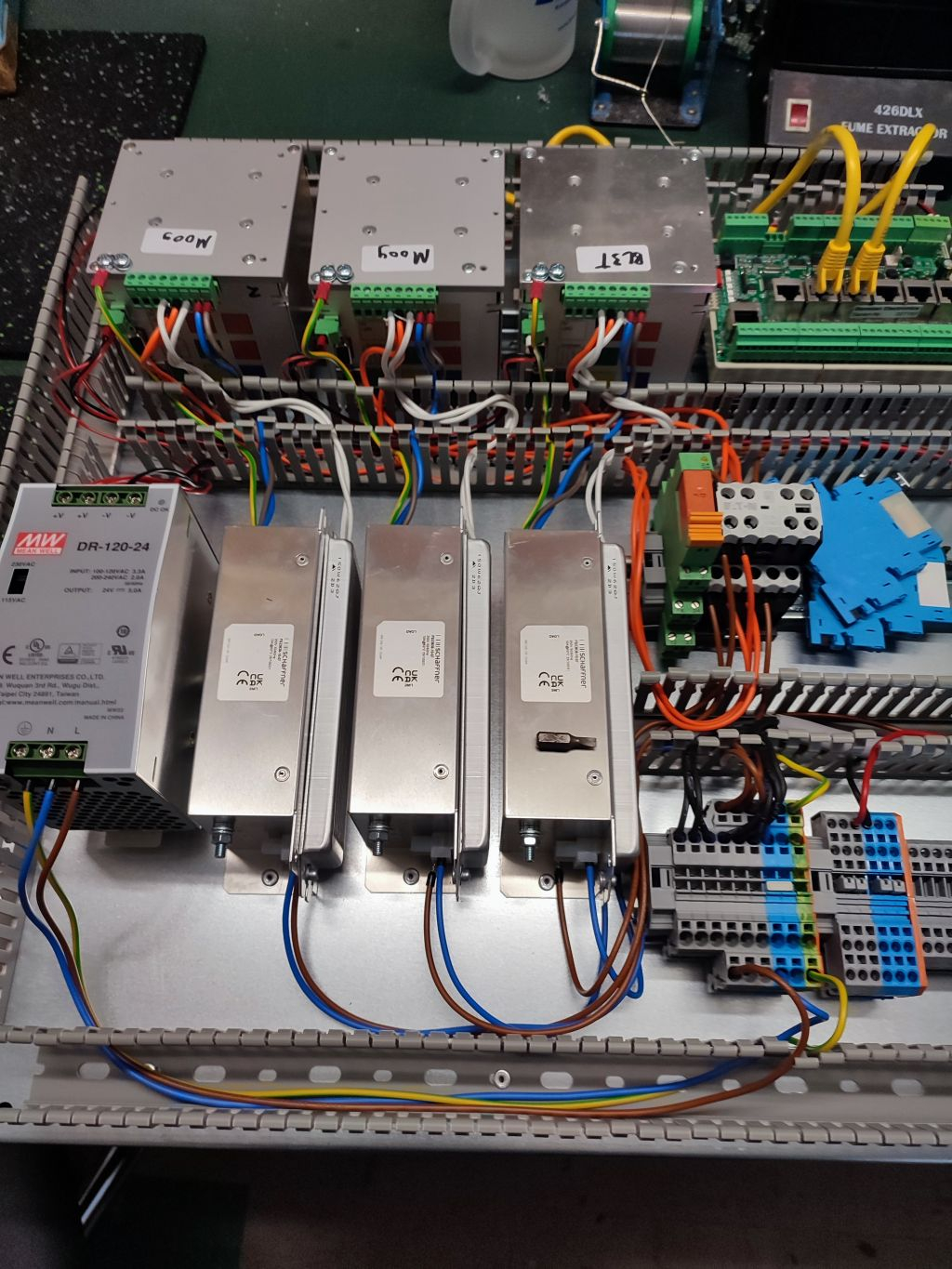
We are currently doing experiments with an ARM based motion controller. I don't doubt that it would be powerful enough to do all the calculations but the documentation is rather poor. So I fear it would be faster to develop a controller based on the P2 from scratch than it would be to find out how the ARM controller works and how it has to be configured. We were able to get one of the motors moving a bit up and down but we haven't managed to perform a proper homing procedure.
So plan B is to use my already existing CNC controller board and modify it a bit for the project. I'll eliminate the stepper motor driver daughter boards and simply output the step/dir signals directly to the servo drivers.
The plan is to use the ethernet jack to connect it to the PC running the simulator software and to communicate using UDP. There is already a motion cueing software available for the PC that calculates the movement of the servos from the simulated trajectory of the plane. So all I have to do is to limit the acceleration, velotity and position range of all axes to protect the rig (and the pilot) from damage.


Comments
Neat!
Though those things do tend to generate motion sickness not unlike VR googles.
I love this project, I love the welding joints - they're pure function (ugly as hell). To me your plan B sounds like a plan A first class.
You'll laugh to death but...it took me minutes of pondering on the fume extractor purpose in this project (why the hell one needs a fume extractor thing where there is no petrol powered engine nowhere to be seen) until I realised it is not a part of the project at all . My mind still surprises me after all these years we spent together.
VR googles generate motion sickness because the visual impression (horizon banking) is different from what your sense of balance tells you (standing straight on the floor). This is like watching a movie inside a car that is driving over a bumpy road but the other way around. If both senses match then you don't get sick. Well... of course only as long as you fly calm and respectful. If you overcontrol the plane or fly acrobatic patterns it's your fault.
For most CNC and motion mechanics, the problem is not strength but stiffness. So the quality of the welding joints doesn't matter much. And although the frame consists of ~100kg of steel it is still far too wobbly. We'll have to insert some sheet metal and diagonal struts to close the open sides of the "wire frame".
Yes, re-inventing the wheel is nonsense from the financial point of view but I always understand and master something much better if I have created it myself.
LOL, I had to search where you saw a fume extractor... But yes, it's just next to the soldering wire on my workbench. The dart board on the first picture also has nothing to do with the project.
BTW, we have installed pneumatic cylinders in the center to counterbalance the weight. Fully loaded with pilot and co-pilot the weight is above 300kg and so the static force of 1kN per motor would be near the continous current limit and probably overheat them quite soon.
I brought that up as a good luck making them match. Tilt doesn't really equal motion.
It's the whole purpose of a simulator that the simulated motion doesn't fully equal the real motion. Otherwise it wouldn't work with limited space. Only the direction of the forces generated have to match. For example you can generate a feeling of acceleration by tilting the seat backwards. This causes the gravity force vector to not go straight down but instead it has a component going to the back of the seat. See explanation here. Moving with a constant velocity cannot be distinguished from not moving at all without a visual reference.
Also check out this for a good explanation of how the motion cueing algorithms work. It's all about filters. So in general...
You're making me laugh. That's certainly not the purpose. That's a limitation.
That's okay. I wasn't trying to dis' your efforts. I do get motion sickness very easy so I'm usually quite happy without the wraparound bells and whistles.
Err, no need to argue or "split hairs". But the limitation is the (main) purpose, in my point of view. It allows to practise flying with limited cost, space and risk while still being as realistic as possible. If you have the money, access to an airport and dare to risk your life you don't need a simulator.
Ok, back on topic. The software for the P2 board should be quite simple. As I said, the PC software does all the motion cueing calculations and sends UDP packets to the PC containing a position value for each servo axis. All the P2 has to do is to check the ranges of theese positions and their derivatives so the axes don't hit a mechanical stop and the velocity and acceleration don't exceed their limits. It then generates step and direction signals for the servos from the velocity (delta position) values. A state machine handles startup and shutdown or emergency stop conditions.
On startup all servos slowly move downward until a homing switch is triggered. After this they move to their neutral center position. When connecting to the PC the position is "blended" from the fixed center position to the current target position of the simulation software to avoid any sudden jumps or jolts. For shutdown the procedure is reversed. The position is blended to the neutral position, then the rig moves to the parking position all the way down.
I'm currently implementing the state machine. The step/dir signal generation is already working. Next thing is the UDP protocol implementation. This should be quite easy as UDP doesn't need any procedures for connection establishment or termination. There are no acknowledges so lost packets are not repeated. This makes everything extremely simple and is ideal for real time data transmitted in small units. Repeated packets would be outdated, anyway.
Very cool. I am surrounded by CNC tube benders (+ welders + powder-coating) and have often thought about a car simulator.
Alas, not enough hours in the day.
Craig
Might be of interest.
https://bend-tech.com/bend-tech-ez3d-software/
Craig
That looks awesome @ManAtWork
Makes me wish I had more room in the house
Yesterday we had the first successful flight with the real sim software (XPlane). This is with the ARM based motion controller. It works but I'm not really satisfied. (The main reason for most improvements...) Although the controller claims to have 2ms update rate for acceleration and velocity control and 550kHz max stepping frequency the motion is awfully jerky and noisy. I'm curious what my step/dir-diagnosis would show if I'd connect it but I'm not sure if it's worth the time. I think instead of analysing what's wrong it should be better to do it right, or in other words with a propeller.
I've already got the PCBs that will replace the stepper motor drivers on my CNC controller.
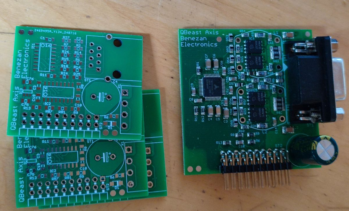
I can't even imagine using step/dir. All the PID is happening in the drive.
I want my drives to be nothing other than commutating transconductance devices.
For me, a simulator needs to be stiff at times and spongy at other times. This is achieved via torque limiting (messing with Kp affects the entire filter).
Look at Cobots. They make contact with something unexpected and they bounce off.
JMO
Craig
@Craig, that makes perfect sense for bending machines and robots. But it's more complicated than necessary for a flight simulator. All it has to do is to follow a computed trajectory. Using torque mode would require more wires to handle the encoder feedback in the motion controller instead of the servo drive. If there is too much torque (obstacle in the way) then it's an error and I shut down.
TherCAT servos could handle all different modes (position, velocity, torque) with just one data connection. But as long as this option is not available I'll stick to step/dir. It's simple, available at all cheap drives and it can do all I need.
Next milestones reached:
I was lazy and haven't assigned an IP address but instead used the broadcast address as destination, so far. I have to check out the ARP protocol if it works so I can assign an IP address to the control board and let the PC know about it.
Ok, ARP is working correctly now.
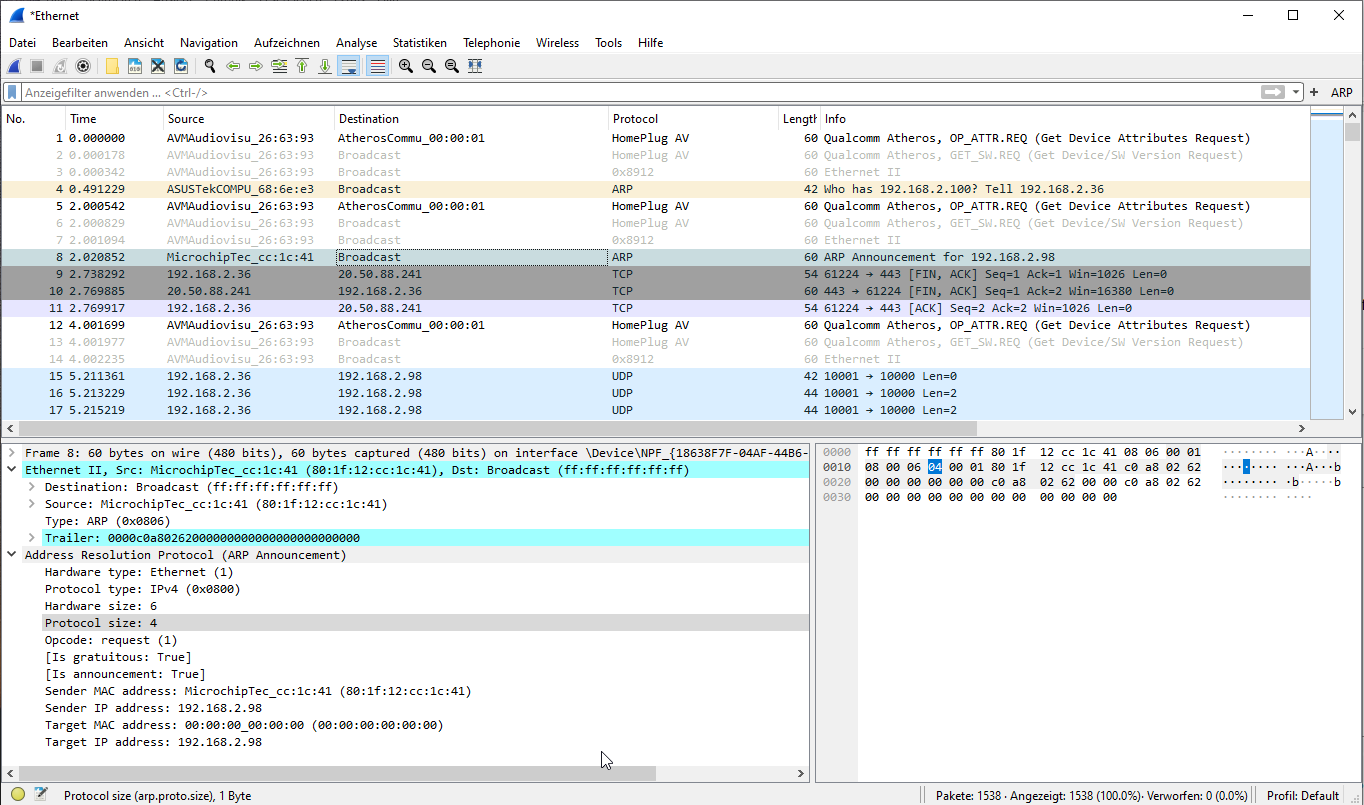
At first, I saw ARP requests and responses in WireShark but it didn't work as expected. The UDP packets didn't come out until I used a broadcast address. It took quite long until I realized that I forgot to swap the byte order (Ethernet = big endian, Propeller = little endian) in one of the header fields. Of course, no big deal for the propeller but you have to remember it.
I'm currently running some analysis to find out why we have so much noise in out motion signals when using the ARM based controller from motion4sim. The servos are silent while standing still or during homing but make a lot of noise when moving. The whole rig rumbles and rattles. I think I've found the possible cause:
From left to right you can see the raw data, id is the identification counter in the IP header, deltaPos is the difference in position compared to the last packet, deltaTime is the difference of the time stamps when the packets arrived and velocity is dp/dt as floating point value. Most of the time the UDP packets arrive quite regular with only small variations of some microseconds around 2ms. No packets are lost otherwise I would see missing numbers at the id counter. From time to time a packet arrives early (for example deltaTime=616) or late (deltaTime=4871). Interestingly, PlyPT Mover (the motion cueing software on the PC) seems to compensate this at least partially by also providing al lower or higher deltaPos so that the resulting velocity stays almost the same.
My suspiction is that the motion4sim controller doesn't account for the deltaTime variations but simply outputs the step pulses to reach the target position as soon as it receives a new data packet. This results in a much higher than necessary variation of the actual velocity and therefore causes lots of vibrations (acceleration discontinuities).
Currently, I'm debugging the state machine for the homing of the axes. I don't know how many times I have written code like this...
    float v= axis->pcmd - axis->pnom;
    if (v > axis->vlim) v= axis->vlim; // clip velocity
    else if (v < -axis->vlim) v= -axis->vlim;
    float a= v - axis->vcur;
    if (a > axis->alim) a= axis->alim; // clip acceleration
    else if (a < -axis->alim) a= -axis->alim;
    v= axis->vcur + a;
    int rem= v;
    axis->pnom+= v + axis->vrem; // add fractional remainder
    axis->vcur= v;
    axis->vrem= v - rem;
But this time I use floating point values for velocity and acceleration. This makes everything much easier because I don't have to care about overflows or loss of precision if the values become too small. The P2 can compute the numbers for all 6 axes in <100µs without any optimizations and in a single cog.

I'm about to implement a kind of "blending" when transitioning from offline to online state and vice versa. While the motion4sim controler needs an extra switch for this I simply monitor the data connection status. If the link is up I smoothly blend to the commanded position with a lower limit for velocity and acceleration. When the target position is reached I enable full speed. If the link is broken I blend to the parking position. This way excessive jolts are avoided and the rig is always in a safe state. No switches required (apart from the obligatory E-stop of course). Simply start or close the sim software.
Aren't there opcodes for clipping in the P2? alas for int not float. or did i dream this (too lazy to look in the datasheet:)
Yes, there are assembler instructions (FGES, FLES...) for clipping integer numbers but not floats. There are tricks such as integer clipping also works for positive floating point numbers as the exponent is stored in the high order byte and therefore automatically has priority for comparisons. But it doesn't work for negative numbers and special cases (NaN...).
But I try to avoid special tricks and optimizations if possible. That might save me from having to code the same algorithms over and over, again. Of course, drivers that are closely coupled to special hardware in the P2 can use assembler as they are not portable, anyway.
Very few controllers have a PVT mode
I wonder....for this application?
Craig
PVT mode, spline interpolation, corner smoothing, acceleration spike reduction or whatever you call it... It's easy in CNC applications. There you have a predefined trajectory and you can apply al sorts of complex math operations because you have lookahead.
With simulators you can't look ahead of time. At least, the motion controller can't, maybe the simulation software itself could as it sees the control input of the pilot before the plane, car or whatever vehicle reacts to that input. But any low pass filtering, spline interpolation or similar things to smoothen the motion would add delay. Delay is bad as it destroys the "virtual reality" feeling as soon as it becomes noticable (more than say 20..50ms or something).
Therefore it is mandatory to have high quality real time data and as little jitter and noise as possible in the first place.
I've made a short video. Sorry, the audio is very soft.

I guess feedforwards are simply not an option with that arrangement, right?

Craig
What do you mean with "feedforwards"? I usually use FF to reduce the following error so that the velocity loop gets fed directly from the nominal velocity value instead of waiting until a following error builds up and the velocity is commanded by P-error * P-gain.
If you speak about the difference of the green and red line, this is something comppletely different. I have to explain that in a bit more detail. There is currently no feedback from the actual position of the motor. That is processed in the servo drive, only (and not at all for stepper motors).
What you see in the scope display are the green line representing the commanded position from FlyPT Mover and the red line representing the output position to the drive. Servos may have additional following error which is not shown. Steppers under load also have following error but with the free spinning motor this can be neglected (<1.8° and <2ms).
I perform some sort of "safety monitoring", that is, I limit the speed and acceleration to predefined maximum values. So if those values are set reasonably the motors can never stall or overload. That is similar to the spike filtering of FlyPT Mover or M4S controller. As long as the velocity and acceleration is within the limits the output follows the input without any delay or position difference. If the limits are exceeded the output is slowed down and begins to lag behind. You see this as the red and green lines no longer match. The red line tries to catch up as soon as possible with maximum acceleration.
You can notice this the most clearly during the parking motion. The nominal position (green) jumps immerdiately to the parking position (theoretical acceleration = infinite). Of course, the actual position (red) can't do that but followes slowly and smoothly in a nice S-shaped ramp curve.
Oh I realise that the steppers are a different story but thinking about the fact that you will be commanding the servo drives via step/dir. Do the drives have FF? I know that some of them are quite sophisticated.
FF is definitely my friend , especially with hydraulics. I am stuck with some proportional valves that have a horrendous dead-band but Acceleration FF does a great job of compensating for this.
This machine I retrofitted; there is a label on the inside of the panel, stating the recommended following errors for each axis (in case of drive replacement). The linear axis (BLM) at high speed? 76mm
 (it's only a point-to-point axis so I didn't even put much effort in).
The drives were in velocity mode. I had to move a solder-jumper on the drive's controller board because I prefer torque-mode and now, with my controller, the high speed following error is 0.2mm
I could never live with an external device handling the PID. It's like trying to wash your feet with your socks on
I see that one of their controllers (6 axis) runs on CAN (?)
I wish you hadn't made me aware of this SIM stuff because now I'm getting hooked

I agree that velocity feed forward is advantageous for CNC applications as it greatly reduces following error. For CNC stuff you want a stiff system and high precision.
But I just have a long debate with the developper of the M4Sim ARM controller about this topic. Velocity FF is the exact reason why I have problems with my servo and this conttroller. He says he doesn't spread the step pulses evenly spaced over the time slice of the computation loop but instead outputs a burst of pulses with a constant frequency (250kHz) regardless of the average frequency (pulses per time sice). Ouch, that hurts. That's effectively a PWM modulated with high frequency.
The cheap chinese drive he normally uses don't care at all. They only count the pulses and apply heavy filtering (~30ms). But my drives calculate FF from the inverse of the pulse period. This is the worst case jitter you can ever have. No wonder the rig shakes and rattles like hell.
Yes, it would be much more elegant to transmit the position values over a digital protocol instead of converting them to step/dir and then back to a counter value in the drive.
No kidding
Well, pretty much only checking the forum for your project so please keep posting. This is gonna be good
Or just use the tried and true +-10V analogue.
What I regard as my best-of-both-worlds is to have the MCU close to the drive, on-board DC-DC converter for +-10v, MC3486 line receiver for encoder signals. All nodes on a 4-wire (full duplex) RS485. But yeah, +-10v motor command is my preference.