

Force feedback joystick
 ManAtWork
Posts: 2,369
ManAtWork
Posts: 2,369
@Mickster said:
Imagine a game with force-feedback (prices are insanely low)
Unfortunatelly, the ali item is not visible in my country. But all joysticks with force feedback I've seen so far are either very poor quality or very highly priced (or both). I'd like to have one that feels like a real control stick of a helicopter. No cheap, floppy plastic.
How about building one by using two brushless motors with gearboxes and a cardanic frame. Applying force with the Parallax universal motor driver board should be even easier than position control. All you need is to output a current vector according to the hall sensor signal pattern.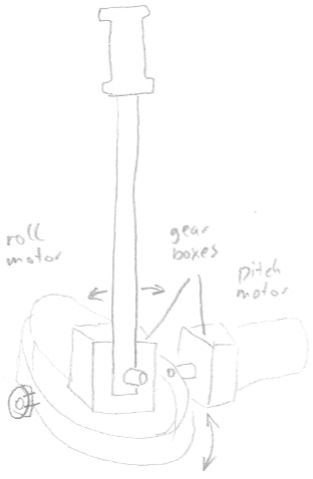
If the motors have encoders they can be use to measure the position. If not potentiometers can be added to the shafts for AD conversion.
Has anybody tried something like this?
Comments
BTW, a "real" servo motor that is capable of controlling position and not only force would be even better. Have you ever seen a drawing of the mechanics of how the two control columns for the pilot and co-pilot are linked in a Boeing 737, for example? There are a whole lot of cables, pulleys, rods, shafts, clutches, springs, bearings etc... and they fill up a lot of space below the cockpit. With two servo controlled sticks with feedback we could make the link electrically and in software so that the other stick follows when one is moved.
Of course, this is not needed for a typical one-man home flight simulator but would enable an instructor & student simulator.
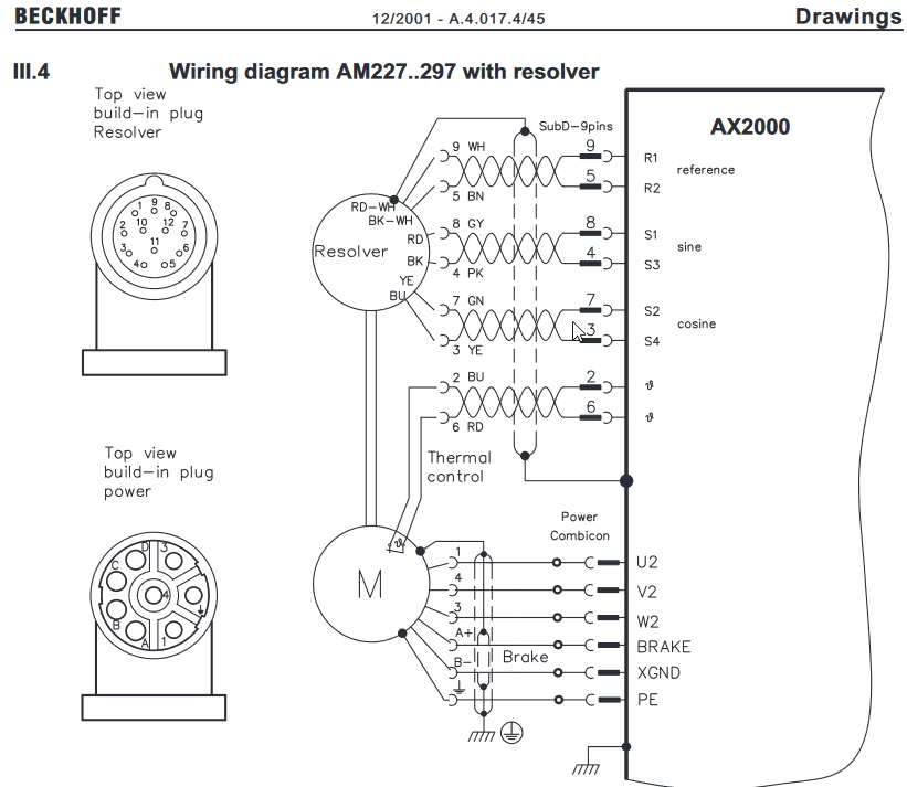
@ErNa I still have one of your servo motors here. The gear has almost no backlash, now detent torque and moves smothly. If I apply 0.6A current I can no longer turn the shaft manually. Do you know what encoder it has built in? I hoped it was a resolver (8 pins = 3 coils + thermo sensor) but it isn't. Must be some sort of digital protocol.
According to this doc - https://download.beckhoff.com/download/Document/motion/am2xx_en.pdf - resolver uses a 12-pin connector and encoder uses a 17-pin connector.
Thanks @evanh , it's really a resolver.") I checked the standard pinout used by most of the other manufacturers (1-2, 3-4, 5-6). But no surprise, beckhoff uses a different standard (5-9, 4-8, 3-7).
I checked the standard pinout used by most of the other manufacturers (1-2, 3-4, 5-6). But no surprise, beckhoff uses a different standard (5-9, 4-8, 3-7).
@ManAtWork
Oh, I was meaning a force-feedback version of the "spinner". I have no idea if that would be useful because I know nothing about games
Resolver to quadrature:
Have you done this with the Prop? Would be really cool.
Craig
@ManAtWork
This is what the above link was for:
@Mickster Yes I've done a resolver-to-quadrature converter with the P1 but it is quite complicated. It uses a filtered square wave to feed an audio amplifier to generate the reference signal. Then I use a 24bit stereo audio ADC to measure the sine and cosine signals. This results in very good resolution and noise immunity. This requires 2 or 3 cogs of the P1 because the quadrature synthesis (+ optional hall sensor emulation for commutation) is quite complicated with the P1 counters. I get around 16bit resolution per rev.
With the P2 I think everything can be done with smart pins. And you don't need to output the quadrature signal to an external servo amplifier but just calculate the position and use it directly. For games 12 bit resolution should be sufficient so we don't need amplifiers or external ADCs but instead could connect the resolver directly to the P2 pins.
Haha, those item descriptions at aliexpress are funny. They try to include as many keywords as possible. But what is that actually? A motor with encoder? Is the speed controller also built in? That'd be really cheap, then. But also not really suited for force feedback, I think.
force feedback needs a very precise current(=force) measurement, much finer than in typical motor control applications
I respectfully disagree. The thought occurred to me because I have small motors on my desktop under PID control and I can make them fight or comply with an external disturbance via variable torque limiting.
Craig
I agree with Simonius if we say "force feedback ... needs a much finer current measurement than the Parallax universal motor driver board has". Unfortunatelly, there is only a 5mOhm (IIRC?) shunt resostor directly connected to a P2 ADC pin without amplification. That is most likely not enough.
However, a "typical motor control application" such as an industrial servo has typically at least 10 bits resolution, high quality drives have 12 bits or more. That should be fairly enough to control the force.
BTW, I'd use something like this:
Brushless motor with gearbox
Probably you could get something cheaper and with additional encoder on Aliexpress...
A P2 should have enough resources to control 3 of such motors (stick roll/pitch + rudder pedals) and I'd have to make my own driver board. But it would be nice to start some experiments with the Parallax board because I have one laying around.
The latest rev Parallax board has the current amp onboard, before the P2 pins.
I just bought one and have been experimenting with it... I think board has one output showing the total current used by the 4 half bridges?
I'm missing something here. My motor current is proportional to the magnitude of my PID filter's output. The encoder picks-up on the disturbance and the PID counters-it accordingly.
Craig
A single Joystick with force feedback would be rather trivial from the view of the control method. A single PID loop controling the motor current proportional to the force calculated by the sim software would be sufficient. Or even a simpler method like a chopper used for controlling a stepper motor... Apply voltage until the nominal current is reached, then wait a constant off-time with slow or fast decay (free wheeling or backward voltage).
A two joystick system is far more complicated. We'd need to simulate a sort of flexible coupling between the two. A small deviation between the two positions should result in a backward force to the moved one and a forward force to the other lagging behind. Damping must be added to avoid oscillations. Force proportinal to the delta position alone is not enough because inertia results in a second-order response. So maybe a full blown nested 3-PID loop system like in a conventional servo is required (position loop, velocity loop, current loop).
I've managed to get readings of the motor rotation angle from the resolver. The first idea was to use the Goertzel mode but then I realized that it's not possible to use two different ADC pins with two seperate accumulators in Goertzel mode. Instead, it's required to use the same ADC inputs (or multiple inputs as differential pairs subtracted or added up) and then apply different weighting for sin/cos accumulation.
The resolver however, works differently. It's a rotating transformer. +sin and -sin are applied to the primary winding. The two secondary windings are aligned 90° apart and receive sine waves with the amplitude modulated by the sine and cosine of the rotation angle. Because the two secondary signals are NOT phase shifted but instead AM modulated the Goertzel mode cannot be used for input.
So I use the DDS output from Goertzel but use two regular ADC smart pins for input. The ADC sample period is half the reference signal period. To demodulate the AM I calculate the difference between two consecutive samples which is the sum of the area of the half-waves. I tried to use a filtered square wave to get more area and therefore I hoped better SNR. But there was significant crosstalk on the 3rd overtone which caused serious distortion of the circle formed by the X/Y values from the sin/cos signals.