

Robot Navigation with Camera and Most Simple Symbol Detection? -- Solution: LinTag5
 Christof Eb.
Posts: 1,597
Christof Eb.
Posts: 1,597
When I experimented with a blinking beacon and it's detection in a series of pictures, it turned out, that it seems to be possible but is relatively slow, because you need perhaps 20 frames. And the camera is surprisingly slow with indoor light conditions. One interesting experience is, that you can simplify the filter process quite a bit, if you choose a special blinking frequency.
The idea is still to have two angles in horizontal direction to calculate the position of the camera.
Normally for object recognition a huge amount of number crunching is involved with KI and learning and edge detection and and and....
But as we are completely free in the choice of sign/symbol - what would be the simplest symbol or rather the symbol, that allows the most simple algorithm to find it in a picture? Unfortunately it's size will vary with the distance.
As we only need the position in horizontal direction I have been thinking about a striped bar. "Blinking within one picture". If the camera is tilted, the filtering could be done along a row. FFT for varying frequencies/sizes?
Other ideas about the most simple sign/symbol to detect?
Have fun, Christof
Comments
April Tags? I have had these in the back of my mind for a long time, but have yet to actually try it.
https://april.eecs.umich.edu/software/apriltag
CMU cam I have claims to get orientation from these as well.
Sorry, I looked it up, it is Open MV, not CMU that has the built-in April Tag tracking.. My info is a few years old, who knows what is available now..
Thanks for pointing me to apriltag. I have read their papers now. (I had already stumbled over this some while ago.) Very interesting! What I do not understand is why they use a 2d pattern. A 1d barcode seems to be simpler to decode?! I understand that qr codes have to be 2d to be compact. But if you only have 12bits of information, 1d should be enough?
I think, for the purpose here, orientation can be assumed to be known, so some form of barcode could be of interest.
April tags are 2D because they're more for determining their orientation and location in 3D space from perspective using a single camera than they are for storing information. They purposely contain so little information so the vision system can focus on figuring out the position.
Yes, 2d because it can determine the 'pose' of the tag. In your application, If the tag is stationary and it's physical 'pose' is known, this can be used to determine bearing (And an approximate distance) to the tag regardless of the 'pose' of the camera. You'd have a pretty good idea of where you are with only 1 tag visible. With 2 tags visible there would be much better precision. If one of the tags is erroneously interpreted the data is likely to be absurd and easily filtered out.
Their libraries look pretty good...
Hm, wondering, if some sort of a barcode as a Manchester Code would be fast to find and decode. Size and deviations in tilting angle should not be a big problem. , it would be attractive, if each row could be processed independently. The position of the tag and its size could be calculated after reading it.
The reason, why I am interested in 1d is, that the picture comes from the camera in rows. As P2 has not too much Ram
Assumption: Tags are mounted on vertical planes and the robot is moving nearby horizontally.
Have to find a good description of Manchester decoding algorithm....
There are lots of good descriptions of Manchester decoding, one is: https://ww1.microchip.com/downloads/en/Appnotes/Atmel-9164-Manchester-Coding-Basics_Application-Note.pdf
Done some estimations: Camera view is 25 degrees with 640 pixels. If we want 3bits payload (=8 different symbols), inverted and repeated for dependability + 2 bits for synchronisation = 8 bits, we need at least 16 pixels. So minimum length of the bar should be >10,6 cm, to be recognisable at 10m distance.
Hm, here they need a long known preamble to find the phase with resolution of 1/32 bit. https://www.analog.com/media/en/technical-documentation/application-notes/AN-915.pdf?doc=an-1182.pdf
"what would be the simplest symbol or rather the symbol, that allows the most simple algorithm to find it in a picture?" --- One trick is to remove ALL common mode information from your image. Basically, create an edge detector filter. You can do this from a single image by taking the image and shifting it by a pixel in two directions (or a polar detection by shifting in just one direction). After shifting the image, XOR the shifted image with the original to create a new image. The new image will show ONLY the differences in the shift, essentially all of the edges. So if you have a beacon with a specific pattern on it, it can be identified easier once you have the edges highlighted
Thanks, Beau, for this input! At the moment I am still thinking in the direction, to "see" a picture coming from the camera as a 1d data stream. The stream are 8bit brightness numbers. One difficulty is to find the threshold value of brightness to distinguish between 1 and 0. The threshold might be different within the picture. Your post makes me wonder, if differences alone could be evaluated? It's time for some experiments....
Christof, Beau's edge detection would make your 1d idea more reliable more reliable. perhaps shift the line a little and XOR. By choosing a 'threshold', you run afoul of noise and shadows. Maybe do an edge detect on your 1d stream by looking for a difference between one pixel (Or a group) and the next pixel (Or group), then if this difference is above (Or below) some threshold you call that the beginning or end of a '1'.
I guess that wasn't underline...
Since you have 8 bit values and not just single bits, you would probably want to take the absolute value of the difference of the original and shifted images rather than just the XOR. The two operations are equivalent for single bits.
Hm, for sure this type of modulation has got a proper name?
Instead of using Manchester Code I will try some sort of "Pulse Duration Modulation": 0=100 and 1=110 So we always have a 01 to gain the clock length and the relative time of 10 will give data. Needs theoretical minimum 3 pixels per bit, but I hope, that with this method no additional pulses for sync are needed. 4bits payload + 1bit parity =15 pixels + 1 pixel=0 start = 16 pixels.
Starts to sound like old Garage Door remotes.. check out this old chip..
https://www.wiltronics.com.au/product/7882/mc145027p-9-bit-trinary-decoder/
Ah, very interesting! So no sync bits needed and they fully repeat the word for security. But they use a bigger difference between short and long pulses. They have the advantage, that the clk frequency is known, though with large tolerance.
Meanwhile, first tests show more noise in the signal, then you would think. Mist? Finding edges is non trivial....
You probably don't need the whole trinary thing, If you get rid of the middle timing and make it binary, you could widen the specs and have a better noise margin. I built a tester that explored the edges of the timing on our product. It didn't take much to bork it up..
All there is by the way of signal processing in those old receivers was a carefully chosen DC blocking cap and resistor (These two components also comprising a low pass filter)
Low pass filter be it physical or digital might help a lot.
BTW, they mainly repeat because the whole thing is that iffy.. the transmitters repeat the transmission several times with even a brief press of the button. You could repeat the pattern on the tag, or compare with subsequent scans.
Yes, in my case the pattern is repeated for several lines, which can be used, so I discarded the parity check bit. But I also now use 1000 vs 1110, for short/long pulses. 100 vs 110 was not clear to discern.
So, tatah, LinTag4 is born, a linear tag with 4bits payload:

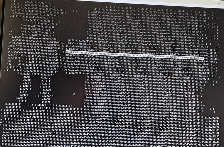
Second picture shows RAW brightness numbers as 4bit hex, zero is blank. Low numbers are dark.
Only every 5th line is printed here and only every 2nd pixel.
The tag starts with LSB and is number 1+4=5
I do think, that automatic detection will be possible and that it can also be done quickly.
1000=short 1110=long
Triggers: Max-4 and min+4
3659b9b85555555555656566889cccc97678888cbcccccccccdcccc976766666777666689acdddd98777878cddddddddddddddd
       D                  U    D       U                D               U      D       U
       Long                    short                    Long                   ´short
The camera has an edge enhancement feature, which is used here, but just a little bit.
Now I will concentrate on the detection code.
Have fun, Christof
Here is a pixel shift edge detector view of your image above as I described earlier ... put that image through your filter and see what results you get

Oh, I should have said, that the scenery fotos have been taken with my mobil phone. And then made smaller with a PC program. Way better than the ov7670fifo attached to P2 kiss board, which gives the brightness data of the other picture.
So yes, I will use edge detection, but I will also evaluate rising vs falling slope and edges are not so sharp. I don't know why.
In my opinion, if you want to use P2, you have to abandon methods, which need megabytes of Ram and due to limited Hub access speed, number crunching must be minimised. So I am working towards a method, which does not even need one line to be in Ram.
Concept:
I think that I need to hold in a ring buffer the pixel column numbers of the last 4 rising and falling edges. 8 numbers. Could reside in Lut. If the falling edges are in regular intervals then it might be a LinTag4. Then calculate position and payload number. Compare with results from last line.
Some progress:
Bright-Dark edges are red, Dark-Bright are Blue, active pulses are green.
Tag position is found quite well. Tag number is faulty some times and there are some fake tags found.
Fake tags and wrong tags can be filtered out, if tag number and tag position must be same for two consecutive lines. Still not easy to make this robust....
wow, that is pretty good. The computationally expensive methods you are avoiding don't work all the time, every time, either. Even those impressive robotic 'conveyor picker' systems with vision systems in the $130K range are averaging the results over a few frames.
https://youtube.com/watch?v=yXNbG4P8fTU
Hm, thanks for the friendly words!
I have spend some time to average a square of 4 pixels. Unfortunately the Fifo is not static and starts to scramble data, if the read clock gets too slow. This type of issue was hard to find... Some assembler necessary for speed.
I think, I should use a longer tag, because "4 regularly starting pulses" is weak as criteria, if anything is recognised as a tag.
Description of the method:
VGA 640x480 lines is captured with Ov7670Fifo attached to P2 Kiss board, as "processed RAW Bayer, CLKRC=$70, Automatic Histogram Exposure, Contrast=$A0, Contrast Center=$FF".
From this every 2nd row is skipped for speed reasons.
From the remaining 640 * 240 pixels 2 * 2 pixels are averaged in a moving average filter, which gives a brightness for 320 * 240 pixels.
Switched to LinTag5, a simplified barcode, which has 5 bits payload, starting with LSB. It has equidistant starts of bars, which enables simple retrieving of the clock cycle or bit length. This is necessary for varying distances of the tags. LinTag5 is read from left to right and has to be positioned horizontally. Length of pulses give bit values:
X000 for 0, X=black 0=white
XXX0 for 1
Made tag higher for more repeat rows.
Enlarged white area before first bit and after last bit.
A complete tag for tag number 10 decimal is 12cm*1.5cm:
A pattern of 5 falling (white>black) and rising edges is sampled in a ring buffer. The number of pixels for 5 falling edges / 4 give the clock rate. Each pixel number between consecutive falling (brightness) edges must be in tolerance to the clock rate. If this is fulfilled, then the pulse lengths are converted to bits and form the tag number.
Same tag number must be recognised at similar column in >3 rows.
In this way the camera can find the tag in a range of distance:
from 23cm with tag width 200pixels
to 87cm with tag width 50 pixels. Smaller is more difficult. At this distance the tag is found about every second frame.
Repeatability of position of the tag is +/-1 pixels.
There are still occasional fake tags.
Capturing the picture in a room takes about 2 seconds, evaluation takes about 3 seconds. The camera needs about 3 frames to adjust exposure, if the brightness changes much. Time for evaluation could be optimised using more assembler.
There are some lessons learned:
1. It is possible to find and locate these LinTag5 with P2 using Taqoz Forth in about 5 seconds.
2. Tag length in the picture is in a range of 50...200 pixels.
3. The method does not have to have a whole frame in RAM. For a moving average brightness filter 4 bytes per column are held in HUB = 320Longs.
4. The Ov7670Fifo camera has AL422B dynamic Ram in it's frame buffer, which gives strange garbled results, if the read clock gets too slow. Fortunately this applies to some kind of average clock frequency, so some heavy number crunching can be compensated by fast reads. Also the OV7670 stretches row time for longer exposure, so frame time has to be long enough using the internal clock divider of the camera.
Have Fun, Christof
Some thoughts about april tags.
https://april.eecs.umich.edu/media/pdfs/wang2016iros.pdf
They use 6x6 Tiles in a Frame of 7x7 Tiles. From 2^36 possible symbols, they only use a very small number of 2221 valid unique codes to prevent false tag detection. (Like the garage door item, which uses most bits together with the known clock frequency to select the one right door.)
In Fig. 8 they seem to claim that they can "see" a row of 5 tags at 0.6m distance and still find tags at 7.0m distance. (7+2) * 5 * 7 / 0.6 = 525 tiles using a 1296 x 964 camera so they need only about 4 pixels per tile.
Their Intel Xeon E5-2640 2.5GHz core needs 0.25 microseconds per pixel for their tags. P2 @ 200MHz with Taqoz needs 37 microseconds per pixel for LinTag5. (Well, for this type of heavy number crunching some native code in cog ram would make sense....)