Building an ESP32 WiFi unit to interface to the P1/P2.
 iseries
Posts: 1,526
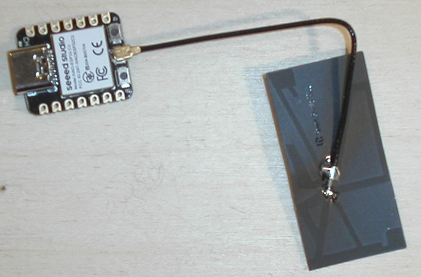
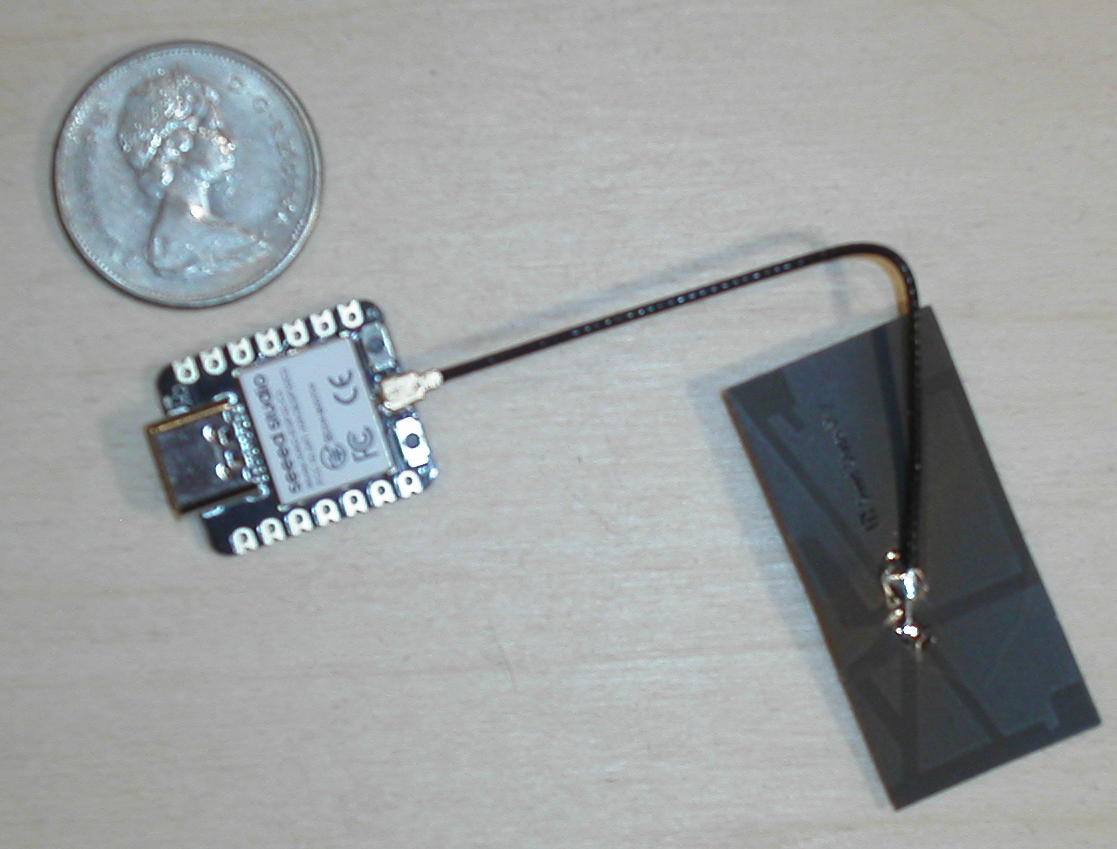
Seeed makes this small ESP32-C3 unit that I thought I should check out and see how it works
As you can see there is not much to it. Only one LED for power and an external antenna that was hard to plug in.
From the size you can see the antenna is bigger than the unit is.
So, what can we do with this thing anyway? Since the ESP8266 there are a number of ESP32 variations available today. Some that have RISC V as a processor.
This means you need a number of different compilers to make all these units work with the same WiFi hardware on the board.
Well, Espressif has packaged that up into a system that allows you to pick the ESP32 chip you have and set it as the target and will build that program from there. Yes, you can use the same source code and build it for whatever ESP32 chip you have.
The IDF build system takes a little to get use to but pays off in the end. They do have a Visual Studio integration, but I prefer building from the command line.
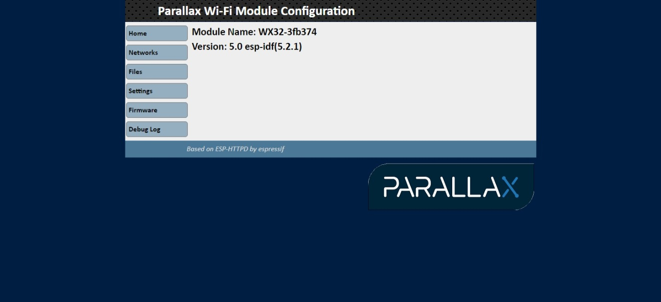
So, where am I going with this? Well, I have ported over the Parallax WX code over to the ESP32 unit and I am about 90% complete with this. I can use the ESP32 unit to function just like the ESP8266 unit for doing WiFi type projects.
With no header pins installed I was able to solder on a few wires and make this a plug and play device.
With my plug and play system I can use the ESP32 as the primary serial device and load code or plug it into a secondary interface and use it as a secondary serial device as well. This works the same for the P1 or the P2 and now with an ESP32 unit.
One problem I have with this unit is that it does not have a USB interface chip so there is no reset line in use and you have to manually put the unit into boot loader mode to load code. It has a USB C interface that for some reason does not let me send data to it, but I receive data from it. Fortunetly the pins for serial communication work just fine.
I have the same code running on the original ESP32 module which is large enough for me to solder wires onto and now on the ESP32-C3 unit.
Still working on a few thinks such as Bluetooth. Can't do code loading with FlexProp as he is checking the version of the WiFi board and doesn't like my version number.
Mike
Oh, and by the way the ESP32-C3 board cost $2.99.


Comments
Neat project, Mike.
The Heltec LoRa 32 is good too
@DigitalBob , for that I used the Grove-LoRa-E5-STM32WLE5JC board.
It interfaced nicely to the P1/P2. I have it hooked up to The Things Network.
Also, the Blues Network Lora board which is only $10. is a great product.
MIke
Although I haven't even tested this yet:
My proposed ESP32 Prop companion
Craig
Ordered a pair going to try them in a point to point application.
Jim
I'm using the Seeed Studio XIAO nRF52840 with BLE for a wearable project, air quality monitors for firefighters. I believe the entire XIAO family comes pre-flashed as Arduino, with configurations to match the on-board hardware, be it BLE or WiFi or both. 11 pins of configurable i/o. Easy peasy if you're satisfied with Arduino. You can reflash to micropython, other options if preferred.
I use the ESP32 to initially provide a "captive port" (a button on the unit initiates this). This allows you to pair your phone to configure the unit via a web page rendered from the ESP32 without the need for using BT. Also allows for Android or Apple phones to connect. Once you configure the unit you can close the captive port. From there the ESP32 does all of the processing, usually pushing/pulling MQTT data to a local broker or into a broker in the cloud.
The ESP32 S3 supports ESP NOW which is a wireless network without Wi-Fi, you can communicate one to one one to many many to one with as many as 20 devices without encryption and something like half of that with encryption.
Good for remote control, device monitoring. The range is ~400 meters. I believe you can use this network while also using Wi-Fi but not absolutely sure.
Details are in the link that I posted previously.
I received my esp32c boards and got the antennas installed. Had to update the Arduino IDE. In trying to get my esp32 up and running, I keep encountering a compile error with the blink sketch. It is looking for a "serial" file that is not found. Any Ideas?
Jim.
@RS_Jim have you seen the following link
https://wiki.seeedstudio.com/XIAO_ESP32C3_Getting_Started/
It details the Blink program and mentions different problems you might encounter in a FAQ
Thanks,
I was finally able to get things to compile after their chat bot had me download and install pip3. The basic blink sketch did not work on either of my modules so back to the drawing board.
Jim.
After a few firmware updates to the Parallax WX code I substituted this unit for my ESP8266 and found that it uses 10ma less power.
Newer chip less power.
I think there is a power option for these chips to set the transmit power, but the WX firmware does not bring this out. Need to look into that.
Mike
Remote weather app link: Remote Weather
Ok , got the blink sketch working by changing to an i/o pin that was actually accessable on the unit. Have been trying to get the wi-fi working but still struggling with that. Sometimes I see the initial web page from the esp but have not yet successfully configured it to connect to my router.
Jim
Really interesting.
Martin
I will have a few questions.
Thanks
Update:
I ran into some difficulties when I did a system upgrade. After the upgrade I lost connection with the ESP32C3 unit and I cannot upload new software to the chip. I deceided that is was time for a major OS upgrade so I partitioned my hard drive and added Linux Mint21 to the new partition. Still having communications problems.
A fatal error occurred: Could not open /dev/ttyACM0, the port doesn't exist
Failed uploading: uploading error: exit status 2
Sketch uses 245078 bytes (18%) of program storage space. Maximum is 1310720 bytes.
Global variables use 9472 bytes (2%) of dynamic memory, leaving 318208 bytes for local variables. Maximum is 327680 bytes.
esptool.py v4.6
Serial port /dev/ttyACM0
At the bottom of the compile screen the port is clearly identified ttyACM0 and if I add a second esp32 at the hub, it is identified as ttyACM1 and I get an error saying ttyACM1 doesn"t exist. I guess my next step is to go find pip3 again and try reinstalling it.
Jim
@RS_Jim ,
There is some talk on the Seeed Studio WiKi about this device not showing up properly or not be able to program it.
Since the device does not have a RS232 controller on, there is no way to have your computer reset it.
Link to seeed: xiao_esp32s3_getting_started
Mike
further update:
I can query the OS about ttyACM0 or 1 and it will find both devices and read back the serial numbers of the devices. I can show them being plugged and unplugged. So that says to me that the OS does indeed know that the esp32s are alive and communicating via serial. I have tried two different versions of the Arduino IDE (1.8 f 2.0) both have the same problem. Unfortunately, I don't have the version number of the os that worked, so that I could revert. @iseries I have looked on the seeed wiki but have not seen the comments about the device. Did you see a solution offered? I will go back and see what I can find there.
Jim
@RS_Jim ,
Because this board does not have an RS232 port but rather a direct USB port there is no way to reset the board or put in upload mode.
There must have been some special boot loader program that came with the unit that you may have lost or not using correctly.
The only way to upload code to this board is to put it in boot loader mode by holding down the boot button and powering it on or hitting the reset button.
Once the code is loaded you cannot use the USB port to send data to this board. It will only receive data from the ESP32C3.
If you setup the board for serial there are separate pins just for serial communication that work just fine. You just can't use the USB port which uses different pins.
Mike
Update:
I received a patch from someone on the A.. forum that patched my OS to accept the serial and now I can communicate with the ESP. Somewhere along the line, it appears that I have damaged my ESP boards as I cannot get blink on any Pin below 7. Pins 8,9,10 will blink an LED but no port below that will. I was having a problem also with Serial monitor, but that proved to be a problem with incorrect board selection in the IDE. I forgot to preface the ESP-32 with XAIO-ESP32... Once I corrected the board type, I got serial working and could output "hello world" from the blink sketch. I need to test pin 0 and 1 to see if I can get an analog input from a joystick into them. Unfortunately, I leave for Canada in a few minutes and will be away from the computer and ESP units for 10 days, so there will be no further testing until I get back. However, I will have the iPad with me and will be able to study code and articles about the ESP-32 so will have notes for testing when I return. I hate to have to do it, but I may have to order 2 more ESP units.
I will be monitoring the forum with the tablet while gone, so if anyone has any ideas, I will see them here.
Jim
Jim,
I don't know if this is what's happening with your pins, but I had a similar issue, then found out later that for my board, the pins were mapped differently under the ESP32 firmware and I was using the wrong pin reference numbers.