P1 counters can you configure a counter to divide a freq on one pin and output it on another?
 Kurt123
Posts: 5
in Propeller 1
Hello
I want to divide a pulse train on one pin and output it on another pin. Looking at the documentation I can't understand counters enough to figure it out.
Any help would be appreciated.
Thanks
Kurt


Comments
Try this one, I used it to read pulse from an rpm sensor and output to a frequency counter
Pin 20 is input, pin 22 is output
you might need this one too
@JonnyMac
@ersmith
According to the AN001 document page 4 the following code:
''Demonstration of NCO counter mode (%00100)
CON
_clkmode = xtal1 + pll16x
_xinfreq = 5_000_000
PUB NCO_single_ended_mode
' mode PLL BPIN APIN
ctra := %00100_000 << 23 + 1 << 9 + 0 'Establish mode and APIN (BPIN is ignored)
frqa := $8000_0000 'Set FRQA so PHSA[31] toggles every clock
dira[0] := 1 'Set APIN to output
repeat 'infinite loop, so counter continues to run
Is supposed to produce a square wave as shown in Figure 3. Using this code I get a triangle wave. Any ideas.
Thanks
Sysclock of 80 MHz (5 MHz x 16) and counter A is configured for NCO Frequency mode (CTRA = %00100) at sysclock/2 (FRQA = $8000_0000). Which means a 40 MHz output. Can your measuring device handle 40 MHz? If not, then you're up for a pile of aliasing (I'm assuming its sampling).
Try this edit:
@evanh
Been a while glad to chat with you again Thanks for the help.
Scope is a fluke pm3062 would have to go look at the specs.
I tried your edit. It worked and my scope is set for 2uS and I have a square wave. Now, how do you calculate this the $0083_12f.
O.k. I think I get the 80 K. Are there any charts that may help ease the pain and what is the formulal used first to get to the 80 k, then to convert to the base 16 and I have searched the forums and internet for the how and why to make this change that is not shown in the AN001 white paper. Would like a source even if it is a book.
Thanks.
I stumbled my way back to the counters and am trying to get a clear understanding of them before I return to the P2 and bumble my way through that. So, if I wanted to experiment and make further changes that are different than the 500th of the clock to say 700th of the clock how do I calculate it. Hope this makes sense.
Also since we are here. I have windows 11 pro. Cannot get the "propscope" to work. Have to go look at the error again. Will let you know.
Thanks.
Martin
P.S. Interesting quote about the AI. Looks like the human brain is still superior.
That's a Numerically Controlled Oscillator function. It works by summing fractions. I like to call them inverse dividers where, instead of the simple integer clock divider, 1.0 has the impossible 32-bit value of $1_0000_0000 ... and 1/2 is $8000_0000, and 1/4 is $4000_0000, and 1/8 is $2000_0000, and so on.
So 1/500 => 2^32 / 500 = 8589935 (rounded up) or $0083_126F.
So I could have also said edit:
or:
Yeah, so note 1/500 is not exact with an NCO. Whereas a simple divider would be exact. On the other hand, a simple divider is poor at selecting a desired frequency that isn't a simple division of the sysclock frequency. The Prop2 smartpins have dual function modes when both a simple divider and NCO can be used together.
.> @pilot0315 said:
What it shows is the huge disparity between the hyped expectations, which impacts management decisions, and what so-called AI can achieve in reality.
I've already forgotten where I found those numbers. I should have put attribution to it ...
@evanh
O.K. that explanation makes sense. , that would maybe show me a bit more in depth of the application side of the NCO that would make sense.

I followed your lead without rounding up and got 0083_126E with same square wave and with the other combinations that you suggested with again
the same square wave.
Now I understand the math.
Thanks.
Next question would be, where do I apply this technique. Can you give a couple of examples. Also would you have a couple of links where I could look at this stuff from a "dummies" standpoint,
No rush. I will be looking for some and try to make sense of it.
My aim is to take the AN001 and go throuh the chapters, find some real world and hopefully relatively easy applications of each type of mode, take notes, file them to get a basic and very basic understanding. I can then move on to other stuff. I think this is the last of the P1 stuff for me to learn and get back to the P2 after my present project is finished.
I am adding an X-band sensor to a custom robot. When that robot is finished I want to now get back to the P2 and the pesky pins with their abilities and hopefully get a good understanding of them so I can move on with other projects. The Pins confuse me. I again recommended to Chip Gracey about having a manual to jump start people on the P2. Something like the old P.E. KIT for the P1. I always have a paper copy and a digital one with me when I am using the P1 for reference. Would like to control the servos with my own code using the cogs as well as use the feedback from the cog to hopefully control the x-band. All will hopefully ported to the Prop C++. I really do not like using libraries without understanding how they actually work and write my own libraries because I do not subscribe to not understand and depend on others to write them. I kinda feel that that is a lazy way of coding. Got to understand what is going on. Libraries may be convienent but the question would be is the libarary used actually correct and a pain to debug. I started on the IBM 1130, 360 in fortran and HP 2000C ages ago in basic.
Again thanks.
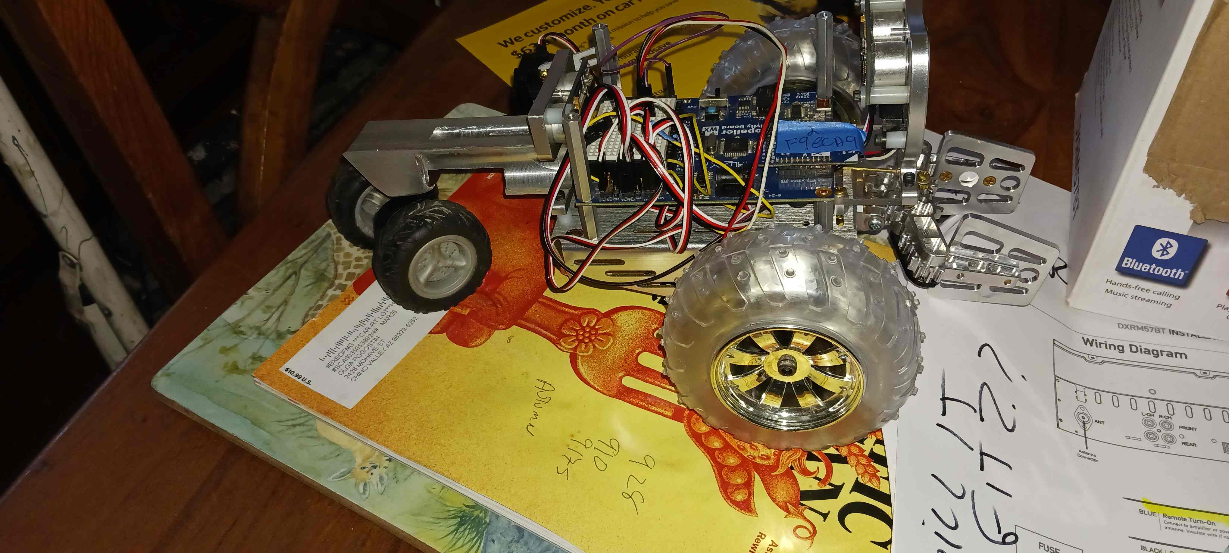
This is the new robot with custom machined tail wheel. Rear and front wheels off a toy electric r/c car from a garage sale. Front and rear pings, infra red distance in front, grabber all of the regular stuff on the WX board. Pending second floor above the WX of clear lexan for harvested from dash cam GPS, compass , 3 axis tilt and a couple of other things mostly from the mystery box from parallax for fun.
A knurled brass counter weight will go where the original tail wheel ball position is.
Next robot is fairley the same but on the tank tracks.
Just having some fun. Then back to the P2 and mayby more robots.
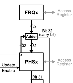
In the first diagram (page 1) of AN001 counters PDF, the NCO consists of FRQx, PHSx, and the Adder between them. The Adder repeatedly, on every sysclock (base clock), sums (accumulates) FRQ into PHS.
The NCO's job is to be like an oscillator - Produce a regular timing, like a clock. What that's then used for is wide open. Over the long average an NCO does well at fractional frequencies but at fine grain timing it is also very noisy. It produces what's called a "dither" to achieve the target frequency. Dithering is alternating, at some ratio, between two discrete widths of a base clock - Sort of like aliasing.

Note: An NCO is not an oscillator itself, it requires a higher frequency base clock input itself. It can't produce higher than 1/2 the base frequency.
I suppose it could be classed as a down-sampler.
@evanh
I sent you a message.
?down-sampler? What is the easiest way to find clear info on this?
Thanks.
Martin
Audio down-sampling is a use case. I just threw in that example in hopes it would give you some context.
An NCO is a fractional divider of another clock. It doesn't originate a clock like a proper oscillator can.
Got it. I will look further. Oscillators are in my next class. Textbook is 900 pages been reading it and the oscillators are the backbone in radio.