

Flash Filesystem and the Edge SD socket
 VonSzarvas
Posts: 3,639
VonSzarvas
Posts: 3,639
Hi all !
With the arrival of the Flash Filesystem, is there any sense to look at moving the Edge on-board SD card onto it's own group of pins, so that files could potentially read/write simultaneously between the devices ? This might as well include hooking in all DAT pins, even if the extra (4-bit) 2 might not be used so often. (Though it might be nice to keep the DAT pin order consecutive... so that leads to the next question...)
Is there any collective preference of which IO pins an on-board SD card might consume? And should the extra 2 DAT pins share with the on-board LEDs if the DAT-to-SmartPin order need not be strict?
And if all that happened, would having a power-cycle signal still be necessary- and if so, then which would be the preferred IO pin for that function ?
Note: I'd expect with such a change we'd want to ensure the DipSwitch settings still allow the ability to boot either from SD or Flash. (Don't think about that for now).
Note2: Maybe a power-cycle (or power-down) could be accomplished by holding the SD card pins in a certain state, to save having an additional pin for that function. Or wire in the card detect pin to an IO, and then use that as a power-down function when asserted low, or as an input to detect the card.
Comments
For ones with PSRAM can that be used as intermediary?
For the other, they way it is on my SimpleP2 board seems to work well…
'Simple1 SD Card Rev3 MISO = 54 MOSI = 56 CS = 57 CLK = 55sure could- at a cost of delay & code overhead
Save anyone looking these up....
EC32 has memory bus where my uSD is I think…
I seem to recall the flash and psram driver (Chip’s) having very small footprints..
But I guess you’d have to flip switches to transfer between usd and flash via psram?
You'd need to enable Flash, that's all.
BTW.. There's another option, just to separate CS. Of course doing that would lead to thoughts about having both CLK's on the same pin; alas that ship sailed")
I think there isn't actually a problem using both together? I think one of the guys figured out how you have to do it to prevent issues. Of course they can't be used in true parallel if they share any pins.
Does this mean the next Edge will no longer be bootable by SD? It would be a shame and a setback to lose that. It works so damn good. I have a stack of Edges that I have never even programmed or used the flash on, because I can do boot and use storage off of SD.
No- it doesn't mean that, don't worry !
Do you (or anyone) know which part was blocking things? I guess either Flash or SD was getting into a state that was holding a pin high?
So if that part could be reset consistently, then yeah, all should be well. That would be good.
If it's the SD card, I guess it's not as simple as doing a reset?... Else this whole topic would never have been "a thing"")
Having a means of getting at the additional DAT pins would be nice, but you can't do it without moving the PSRAM pins (since the data pins need to be able to have CLK as their B input). At that point it'd be a completely different and incompatible thing. Or you duplicate all the SD pins elsewhere, but then, why not just use an external socket... All very difficult.
And I'm not sure I mind that. Arguably, I think of the two scenarios, far more important to allow parallel access to SD and PSRAM, instead of SD and Flash.
Ultimate simplicity would be a single accessory that maps all SD DAT pins, has a power-cycle function, and losslessly buffers P58 (DO..MISO). Plug into programming port for SD booting, or any other port for conflict-free bulk storage.
The SD socket on the Edge modules then becomes redundant for customers willing to buy the accessory - that space on the module could be swapped to a BLE module.")
I want to say @evanh was working on this
Certainly!
Or maybe just get rid of the flash/SD dichotomy... They make "SD NAND" now, which is just an SD card in an 8-pin package. Downside is that you can't really take that to your computer. And Chip will be sad after investing so much in flash wear levelling.
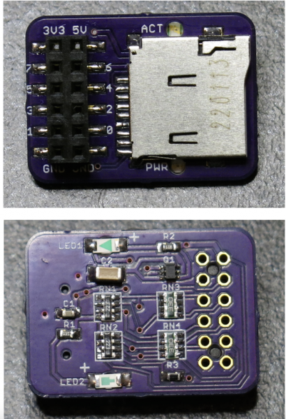
Sure, take a look here. My schematic worked although the pFET choice was a little on the low power side and could potentially be beefed up in a better implementation. Also provided LEDs and power on/off control plus card detection with its full 8 pins. Seemed to still work out ok for the few cards I used and @evanh and I saw some very fast performance in 4 bit modes in some initial read tests...
https://forums.parallax.com/discussion/174988/new-sd-mode-p2-accessory-board/p1
It doesn't address your pin sharing thing though, as it was designed only an accessory board and as such you can't necessarily boot from it directly, although you could boot from flash first then via this board if you really needed to. It needed a mod to evanh's optimized SPI code to allow pin spacing in 1 bit mode to still work in flexspin, hopefully that made it into the main line of code by now, not sure.
That is not an available option in the case of a reset and reboot since the ROM code needs to detect the soft pull-up of any SD card presence before it'll attempt any SD ops.
What actually seems to work reliably is a combo of two practices in the SD driver code:
Both are needed for shared access to an EEPROM anyway. It just happens they also leave the SD card in the right state for a rebooted ROM code to detect SD card presence, which will then issue its own CMD0.
PS: The official SD docs also state, in case the SD card is not back to idle, a power control switch be used to power cycle the SD card during card detect sequencing. Obviously this would demand an extra control pin from the Propeller. Roger has this feature on his add-on board since there is eight pins allotted to those.
PPS: One of the limits of the shared pins arrangement is Parallax has added an inline current limit resistor to the MISO (DAT0) pin of the SD card slot. This caps max data rate to around the spec'd 25 MHz of high speed mode. Otherwise, SD cards seem to be happy to overclock a long way (> 100 MHz), even in SPI mode.
Following.
please just "yes", "no", "not exactly"
Are these sentences correct?,
2."during a copy data from the SD card to the flash or vise versa; the data flow is constantly being interrupted due to changing which part controlls the DO line"
3." If the DO line for Flash was different than that of SD card, would the data rate be significantly be faster"
My thinking if my assumption of how data is read from the SD card is "block by block read". is that sentence 3 would not be true because of still needing to write to the SD controller to request each data block; which would also interrupt the SD controller from sending data to the Flash. If the pins were sepperated would the data rate be hugely improved or not really by much if at all given that the same block read commands still need to happen. If data is sequentially read from the SD card, the read commands still need to be sent to the SD controller. I am wondering which is faster the P2 or the SD cards own controller
For answer #3, yes, it is possible to operate concurrently. But as Roger says, you'll be needing to write the code to do it that way. Eg: Since the driver code is just direct functions that hit the hardware, you'll need to start a fresh cog for your code calling to the second device. This way both routines can transfer to/from respective hardware concurrently without worrying about trying to time slice the tasks.