I2C Woes
Probably not the right place, but looking for a little assistance.
Working on a project, and I'm many years removed from embedded systems (my last major project used BS2/P1).
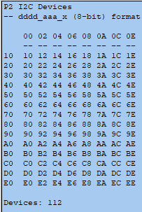
Using a P2 Edge Module and P2 Edge Breadboard, and the jm_i2c_devices object. I had to change the jm_fullduplexserial.spin2 to a different variant (the one inclued in the ObEx package uses a variable named 'field' which seems to be a reserved word). After making necessary corrections, when I compile and run I get the attached output indicating an I2C device is present every possible I2C address.
I've tried SDA and SCL on different pins, no pullup resistors, 4.7k pullup resistors, 10k pullup resistors, three different I2C slave devices, even with no I2C slave, and the same result every time.
I'm fairly certain I'm simply doing something not quite right (but after a couple days of reading and relying on my really old memories, I'm stumped), so if anyone has ideas or suggestions, I'd love to hear them...


Comments
Since my name is being bandied about, let's make sure you have my latest code and libraries.
Thinking about it for a moment, the code looks for an ACK indication from the device which is a low level -- if your bus pins are always low then this could give a false positive. The I2C object lets you set internal pull-ups. If you don't have them on your device.
Hey Jon...
I really appreciate you chiming in! I wasn't calling you out! While I admittedly don't understand all of your code, it's something I understand enough of and am comfortable with and greatly appreciate your efforts and sharing with the community...
Thank you for sharing the latest code, I've downloaded and tried it...
Just to do a quick test to see if the results would change, I just put 4.7k pull-up resistors on both pins (I'm using 54 and 55). The result is different, although I'm not sure I can entirely explain it. I had no particular expectations other than it looking like it's actually trying to do something, which it seems to be. I'm going to add in an I2C slave and properly configure things to see if that makes it behave properly.
Thanks again for sharing the latest code.
I'm not sure what's going on with your circuit. I'm on the road, but happened to have an Eval, one of my custom P2 accessories that has a Qwiic connector, and a Qwiic-compatible temperature sensor board. Here's the scan using pins 54 and 55, with the pull-up parameter set to PU_EXT.
The sensor is correctly identified. I unplugged the board and changed the pull-up parameter to PU_15K. Here's the scan result.
It's what I expected: with no devices attached there is never an ACK bit (low) at any address.
One thing to double check.... are you using the P2 Edge, or the P2 Edge 32MB version ?
-- (If using the 32MB version, then only IO pins 0 to 39* would be available- try moving your test to within that range)
Also, could you post a photo of your board?- in-case any clues can be spotted!
@9Escott if u r feeling adventurous, you could try the spin2 code generator:
https://forums.parallax.com/discussion/175417/spin2-code-generator-work-in-progress-most-things-working
Just tell it pins and pick pull-up options and it will write working i2c code
Viola! Thanks @VonSzarvas, that does in fact seem to be the problem. I am using the 32MB edge...I was completely unaware that not all I/O's were available. Switching to I/O's 14 and 15, things run as expected. I'm sure this is documented somewhere, and the reasoning of limiting I/O availability...so save me the time searching, to you happen to have a link or reference?
@JonnyMac Thanks for your insight and input, greatly appreciated.
@Rayman I'll check it out...it's been a long, long time since I've written anything in Spin, and never Spin 2 (before earlier this week)...so I'm sure your code generator will come in handy!
Pins 40 through 57 (18 total) are consumed by that 32MB RAM expander. They're not connected externally to improve signal integrity. P40 through P55 are the 16 data pins, P56 is clock, P57 is chip select.
This is documented right there on the board: "8 CORE 46 I/O +32MB" Unlike what @VonSzarvas said, pins up to P39 are generally usable. P38 and P39 have LEDs on them, as you may have noticed (but they can be turned off with the DIP switch).
Thanks for correcting - I've updated my post above.