

Sony Infrared Protocol Help
 Quang
Posts: 2
Quang
Posts: 2
Hello,
Happy New Year!
Please help on generating proper signal for SIR protocol. I'm want to write the entire code in PASM. So far with the P1, I am able to generate the logical "1" signal at 1.2ms and a "space" signal at 600us. However, for some reason there are other signals that follow the "1", and then the "space" signal.
I've attached a screenshot of the logic analyzer.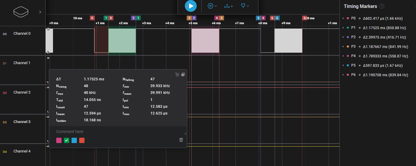
On the picture, the "1" signal is between the #1 flags. The "space" signal is between the #5 flags. Signals between #2, 3, 4 flags were not intended, I'm not sure where they're coming from.
Also, it seems the "1" and "space" signals are in reverse order?
I'm working on the code little chunk at a time, so I'm just trying to send the "1" and space right now. I think if I can get this working, I can try for the entire protocol.
I've read through OBEX's projects and Discussion Forums but found little reference to PASM pertaining infrared protocol. I'm also very new to the electronic world, so if I missed any sound advice, please point me in the right location.
Thank you in advance.
Quang


Comments
I've been writing SIRCS code in assembly since the days of the SX chip and we had to use an interrupt. The process is the same, though (which I'm sure you understand)
You can use a cog counter in NCO mode to create the desired LED modulation. You can control this modulation being on or off using the DIRA bit for your output pin.
At work I design and code laser tag weapons and accessories that use Sony IRCS bit encoding for the laser tag "bullets" and command packets. The attached object is generic and can be used to send for general Sony IR control. In the test I sent $AF which you can see is output LSBFIRST. Again, normal SIRCS commands are 12-, 15-, or 20-bits, and are usually repeated 3 to 5 times. The tx() method in the object gives you full control of those parameters.
JonnyMac, thank you so much for your advice and example. I will study the example carefully. This is a great guide on learning to write Assembly language for the Propeller.") .
.
I definitely will have a different perspective next time doing laser tag
I'm glad I could help. Have fun.