Of course not. According to the hacker's code of honour no intelligent person who is able and willing to be creative should ever be forced to do boring work for solving problems that others already solved. That's what libraries are meant for. It's completely OK and recommended to use them if they do what they should and don't bloat the code more than necessary. I only meant to blame those programmers who don't really know how to program but just call functions of libraries other's created. That's still OK, or to use Ada's analogy, there are bands that only play cover songs. Some of them are really good. But there is software that is ridicously bloated or inefficient because the programmers know nothing about algorithms and use big libraries because they are lazy.
The setup software for Yaskawa VFDs are an example. The tool needs >4GB to download. After installing it it takes minutes to load and then tells you to download another couple of GBs of updates. And all that only to set some numerical values over USB.
OK, I think I begin to understand the mailbox protocol. It's really sick. The CanOpen protocol used to be designed for the CAN bus, of course, which always suffered from bandwidth drought. They squeezed the complete header (type, size and some status bits) into one single byte! Depending on the command type the size field has more or fewer bits. They re-used some of the command types depending on if its a request or response. So you always have to watch out what it means depending on the communication progress and context.
But after I've corrected a few mistakes I finally get some results. The watchdog cuts the connection and resets the state of the state machine to Init if it times out. But it doesn't clear the SyncManager registers. They are write protected once the Sync Manager is activated. So I can't write to them in all but the first session if I don't clear the "activated" bit before writing.
Address a=03e8:1000 is the outgoing mailbox and a=03e8:1200 the ingoing mailbox. The final result indicates that I have read $66668888 from service data object index $1018 subindex $01 which is the vendor ID of JMC (servo manufacturer).
Oh man, I need a beer.
The setup software for Yaskawa VFDs are an example. The tool needs >4GB to download. After installing it it takes minutes to load and then tells you to download another couple of GBs of updates. And all that only to set some numerical values over USB.
Except that it won't connect or you get a bunch of nonsensical errors. Supplier offers to take control of your laptop via TeamViewer and that starts a war with "the IT guy" who doesn't want to provide access and when you finally get it, the WiFi signal is too weak to support a TeamViewer session
Some slow progress: I can also write SDOs, now. But sometimes the mailbox buffers get messed up and the communication stalls.
The mailbox mechanism is actually quite clever. The ingoing and outgoing mailboxes are buffers in dual ported RAM which can be accessed both from the network side and from the slave microcontroller. Access is automatically interlocked. When the last byte is written from the network side the buffer is transferred to the slave controller side and further access by the master is blocked. When the slave has read the last byte the buffer is transferred to the master side again and writes are re-enabled. The same mechanism is implemented in the opposite side just with read and write access reversed.
Each datagram has an index counter that is incremented for each communication cycle. So theoretically lost packets could be detected automatically by missing numbers. But because it's unclear if the original (write) data packet or the response (read) was lost the master could accidentally repeat a packet that was actually written to the mailbox. Only the returning packet was lost. But the false repeat could also be detected by the index (same number). But automatic error handling would require some interconnection beween the write and read mailbox logic that was never implemented. So if something goes wrong the interlock mechanism that should originally help does actually make things even worse. You have to set a special "repeat request bit" in a register or clear the so called Sync Manager (buffer interlock handler) manually and start all over, again.
@ManAtWork
What's really frustrating when undertaking such developments is not having someone to bounce ideas around with. So thus far, you haven't needed anything that is proprietary to Beckhoff?
@ManAtWork said:
The ingoing and outgoing mailboxes are buffers in dual ported RAM which can be accessed both from the network side and from the slave microcontroller. Access is automatically interlocked. When the last byte is written from the network side the buffer is transferred to the slave controller side and further access by the master is blocked. When the slave has read the last byte the buffer is transferred to the master side again and writes are re-enabled. The same mechanism is implemented in the opposite side just with read and write access reversed.
Is that automatic interlock applied to the whole dual-ported RAM and thereby only handling one packet at a time or does it provide multiple independent locks for concurrent packets allotted across multiple buffers at once?
@Mickster said:
@ManAtWork
What's really frustrating when undertaking such developments is not having someone to bounce ideas around with.
Yes, my comments here are probably not of much real use to anyone. But sometimes I need to discuss the problems with myself. To formulate and write down my thoughts helps to clear my mind and possibly find solutions I haven't thought of earlier.
So thus far, you haven't needed anything that is proprietary to Beckhoff?
I haven't used any part of their source code if you mean that. Of course I have needed the protocol specifications to look up the theory and algorithms. BTW, I've found out that the servo drive manual from SanyoDenki explains much better how everything works. They provide a step-by-step procedure with a flow chart of how everything has to be setup for operation. The "conspiracy" theory behind that is obvious: Beckhoff wants to sell their training courses and consulting. So they don't want you to be able to figure out everything on your own. SanyoDenki wants to sell their drives. If you get them operational faster than those of the competitors it's to their advantage.
@evanh said:
Is that automatic interlock applied to the whole dual-ported RAM and thereby only handling one packet at a time or does it provide multiple independent locks for concurrent packets allotted across multiple buffers at once?
There are multiple Sync Managers (interlock units) per slave and each controls only a subrange of the available RAM. Two are used for the ingoing and outgoing mailbox for the SDO communication. Another two are used for the PDO communication. SDOs (service data objects) are used for one-time initialization and are not time critical (for example control loop gain). PDOs (process data objects) are used for cyclic transmission of real-time process data (for example target position and actual torque). Multiple PDOs can be mapped to the PDO buffer memory.
So only one SDO can be handled at a time per slave. But that's no problem because the SDOs are not time critical. The communication mechanism for the PDOs is very efficient, though. Up to 4 times 12 PDOs can be mapped per slave and all PDOs of all slaves can be transmitted in a single Ethernet frame for both write and read direction (if they fit into 1.5kB, of course). So the whole initialization process is very complex. But once everything is set up and runs it is very efficient.
Until now I have processed all commands one-by-one meaning that every single read or write transaction was translated to an Ethernet packet with a single datagram in it. This was easier to debug but terribly inefficient, of course. The EtherCat master should be able to bundle multiple commands into a single packet and process them concurrently. So I changed the linear code to a state machine. There are multiple FIFO queues for new commands to be processed, those that are waiting for reply and those that timed out and need a retry. The state machine looks if there is something to do, builds the datagrams and sends them all in a single packet.
I still need to debug this before proceeding to the next step: setting up the distributed clock system for synchronisation of all slave devices.
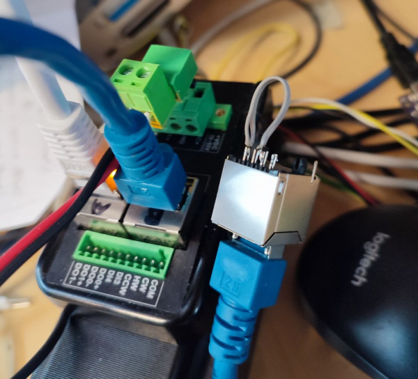
I have extended the Ethernet PHY driver to record timestamps for sending and receiving network packets. Each slave device also latches the local time when a packet arrives at any of its ports. Each packet is passed from the master to port0 of the first slave, processed internally by the EtherCat processing unit, sent out at port 1 to port 0 of the next slave and so on. If a port is closed (nothing connected) the packet is looped around to the next open port. The last slave has only one cable connected so any packet that arrives at port 0 is looped back and sent out at port 0 again to the previous slave. This continues until it is sent back to the master.
As I only have one slave device at the moment I've closed the loop at port #1 with jumper wires.
Now I can measure the timing of the packets travelling through the loop.
The total round trip takes 3170ns. This includes the smart pin shift registers of the P2, the delay of the Ethernet PHYs and the EtherCat processing in the slave. The "time of flight" in the last cables including the PHY delay of port #1 out & in is 600ns. If I add 2m (=4m forth and back) of cable I get 640ns.
It's been quiet for a while but that doesn't mean that nothing is done. I have decided not to rush for an ASAP "get the motor to turn" solution in free running mode instead of fully synchonized distributed clock mode. This does not only require to measure the delay of the packets travelling through the cables but also adjusting the clock speeds so that there is no long-term drift due to the tolerances of the individual crystals. To compensate the drift the time differences between the local and the refernece clock is measured. This is fed into a PID control loop of which the optput "tunes" each local clock by adding a small fraction (up to 100ppm) of the time passed to the clock. This works, now.
We also had to do a new layout for the slave board (see post #1 right side) to change the P2 pinout and add an EEPROM for the configuration data.
I discovered a strange thing: one ethernet packet is lost exactly once every 100ms. I haven't figured out what causes this, so far. I thought it could be a watchdog inside the EtherCat device because 100ms is the default timeout. But I've changed the watchdog clock divider and the 100ms stayed the same. And I don't think it's related to noise or EMI. We have 50Hz mains AC frequency so it should be much more likely to happen every 10 or 20ms. I also doubt that it's a bug of my Ethernet driver. No counter overflows at a 10Hz interval. If I send a packet every millisecond then the lost packet ratio is 1:100. If I send every 10ms it's 1:10.
I need the slave boards to check if it's a bug in the chinese servo drives.
Another piece of hard work shows some progress. I can parse the XML files, now, that contain the descriptions of the device properties like mailbox buffer sizes, timeouts and the SDO/PDO object dictionary. I have coded this all from scratch because I need full control so that only the relevant information is passed from the PC to the P2. Storing and parsing them on the P2 would require an SD card interface and lots of time. As I mentioned before the files are really big, several megabytes per device.
However, it's making me less and less a fan of such a ridiculously complicated network. I'll stick with RS422, 4-wire with a simple protocol (KISS principle)
Everything evolves messy. I've been shifting some Modbus on RS485 equipment over to ModbusTCP on Ethernet, and that offers 32-bit "registers" but only in a wacky ordering and addressing way. I'm guessing there's some sort of compatibility reasoning but am just going with the flow and not delving into the why's really.
It absolutely does and I don't understand why. Too many cooks, I guess.
I am convinced that the industry giants are inventing complexity and convincing the market that they really need it.
I lurk here and all I do is SMH. All of these problems don't need to be.
Yes, that happens quite often. Same thing with "Eagle" (PCB layout editor). The acronym stands for "easy applicable graphical layout editor" and 20+ years ago it was exactly that, easy to use, compact and efficient. I think the original software was written in 386 assembler and was quite fast on VGA. Then Autodesk bought the company and now it's bloated and painful to use. The footprint libraries are so big that it takes several seconds to load even on a fast PC and you don't find anything. I still use the old version from 1995 which luckily still runs on Windows 10. The VGA stuff is now emulated which means that the screen update is actually slower on a modern 3GHz PC compared to a 12MHz XT it was designed for.
The problem is that big companies always try to please everyone. This leads to every project passing the magical "one man knows it all" threshold. Once the "critical mass" is reached the complexity grows uncontrollably.
Back to EtherCat... I still hope that the whole complexity is only required for configuration. All that megabytes of XML files and SDO object definitions only really matters for an expert who needs to figure out how each device needs to be configured, i.e. which value needs to be written to which register or "service object" to get the thing running. Once this is done everything gets easy and works very efficiently. It all comes down to two buffers, one for the inputs and one for the outputs. The first n bytes of the output buffers are mapped to the first device, the next m to the second and so on. The output buffer is sent out to the network cyclically and automatically and the input states are received and placed in the input buffer. It behaves like all the I/O was connected directly to the master and the buffers were just a bunch of hardware registers.
Fortunatelly, all servo drives behave very similar and the layout of registers or PDOs (process data objects) is mostly the same. Example:
object 0x607A is the target position,
0x6064 is the actual position,
0x6077 is the actual torque.
Of course, every motor is different. The maximum current, torque per current factor, encoder resolution and so on are different. But that's not a problem. Torque for example can be displayed as a percentage of the nominal value so everything above 100% means overload. It's the same as every Boeing pilot can sit down in the cockpit of any Boeing plane and can tell from the engine diplay if the engine is performing like it is meant to without even knowing which engine type is actually installed. An N1 of 90+% means takeoff thrust and ~30% means idle no matter to what actual RPM that corresponds to.
My plan is to provide a library of hardware abstraction files for "known good devices". They only need to contain a dozen or maybe 20 values. An expert who knows how the servo drives and the EtrherCat setup works can add new devices to the library but Joe random user doesn't need to. He can just plug in the cables and the software looks up in the data base if the connected devices are in the library. If they are then everything configures automatically. All the complex EtherCat protocol runs in the background and the user doesn't need to care about. At least that's the goal.
Servo drive. I don't care, old/new, any brand as long as it can be set to torque-mode and has an analogue command. All it needs to be is a transconductance device that commutates. My controller handles everything else.
See these guys on the plant-floor, hooking-up to devices with a laptop, trying to remember how to use the setup software, what's the password, who has the proprietary 485 cable with the weird connector.
@Mickster said:
See these guys on the plant-floor, hooking-up to devices with a laptop, trying to remember how to use the setup software, what's the password, who has the proprietary 485 cable with the weird connector.
Yes exactly. My plan is to make any custom setup software and proprietary cables unnecessary. The cheap chinese drives offer EtherCat connectivity but still need a serial port and PC software to tune them. But the more user-friendly and higher priced drives from the big names (Sanyo Denki, Yaskawa, Panasonic...) have ALL tuning parameters accessible over EtherCat. This not only means that they can be tuned online with the same software that runs the machine. It also means that it's no longer required to "customize" each drive by storing parameters in it which limits their use to a particular axis in a particular machine if you don't know how to change the parameters (which overstrains most users).
If all the parameters are stored in the master controller then if one of the drives breaks down I can ship an "empty" drive to the customer. He just pulls out the connectors, replaces the drive, plugs the cables back in, switch the machine on and it works, again. That's a BIG advantage and makes service and stock of replacement parts much easier.
If all the parameters are stored in the master controller then if one of the drives breaks down I can ship an "empty" drive to the customer. He just pulls out the connectors, replaces the drive, plugs the cables back in, switch the machine on and it works, again. That's a BIG advantage and makes service and stock of replacement parts much easier.
AAArrrggghh! I have totally forgotten that I actually have a 100ms period in my Ethernet driver. It frequently polls the PHY status register to check the link status. This register is accessed over the SMI (serial management interface) which shares pins with the RMII. I still have to find out what the exact problem is but somehow those status polls interfere with the network data transfer and seem to cause the loss of one packet per 100ms.
But after all, that bug wasn't all that bad. It has helped me finding at least three other bugs which only showed up due the packet loss. First, the repeat request of the mailbox protocol was not handled correctly. Second, a cyclic datagram was not re-scheduled if is was sent together with a non-cyclic datagram. The third bug was a rather stupid one:
        uint8_t match= task->number - dataHead->index;
        if (match < 0) EnqueueTask (&RetryTasks, task); // task older, frame was lost
        else if (match > 0) break; // task not found, abort
        else { // index match
Of course, uint8_t is always positive so the function after the first 'if' was never executed. I deleted the 'u' and it works as it should, now. So I can pretend that the packet loss was there intentionally as a stress test of the robustness of the protocol.
every dump guy at least can serve as a bad example! ;-) Everything is fine as long as you do not connect +25V to the Vcc ;-)
Just to be more precise: I made an setup for an upcoming demonstration and to be sure, that all the wires are properly connected, I reordered them and in doing so, I connected the +24V to the wrong row, so as I switched on the power, the power switched of a lot of IC's! And now I look for the upside ;-)
Now that I can initialize the distributed clock, the Sync Managers and the FMMUs, read and write SDO objects and control the state machine I thought that the rest would be easy. But I'm stuck at the moment. The servo refuses to react as expected. It simply returns zero data or responds with weird error codes, for exaple "value out of range" when I set the operation mode to 08 (synchronous position mode), the same value that is given in an example. I spent a day reverse engineering the comunication of EC-Engineer (PC software) with Wire Shark just to find out that it does the exact same thing as I do (AFAICS). But EC-Engineer works, it gets no error codes but valid position values. So I must have missed something...
The only difference I noticed is that EC-Engineer initializes all four RX and TX PDO mappings although only one of each is actually activated. In the list of initialization commands when I select the three "redundant" mappings the delete button is disabled. So they must be marked as "mandatory" somehow although they are not used or activated.
But that's something I learned for this project: "Don't ask if it makes sense"! Instead, just do it as everybody else does it. ... "You will be assimilated. Resistance is futile"
The funny story continues. Some more of the few hairs left on my head are turning grey...
I found out it had nothing to do with the unused mappings. But now I'm at least able to write the operation mode and switch to Safe-Op state. This is one step further than before but I'm still not really happy. I don't understand what the actual problem was. Until now I was thinking I had to do some initialisation and then request switching to the next state. The slave controller then should check if the configuration is valid and if this is true acknowledge the requested state change or throw an error code if not. At least I thought that's why there is a long timout to wait for the acknowledge. But that's not how it works. It seems that the order of the initialisation write accesses is critical and some depend on other actions required to happen before.
If I just switch to any of the available operation modes I get an abort code. But I can switch to contour profile mode (01) if I clear the sync mode before (so called "free run mode"). IMHO it makes perfect sense that I can't switch to synchronous position mode (08) if synchronisation is disabled as it requires synchronisation as the name implies. But there is no documentation which of both settings have to be done first. And from the WireShark log I can see that it works even though EC-Engineer switches to synchronous position mode even before setting some important parts of the distributed clock unit such as sync cycle time. I just don't get it.
Anyway... the fact that I can activate contour position mode without synchronisation but I can't activate cycle synchronous position mode leads to the conclusion that there must be something wrong with my clock&sync setup procedure. I have to keep searching.
The motor still doesn't run but I have found a really nasty "mistake", or how should I call it. I'm still not convinced that I did anything wrong but the servo obviously is. To explain this I have to go one step back and first describe some of the previous bugfixes. Some registers require a special order for writing them. For example, the SyncManager registers are writeable only while the units are deactivated. So clearing all registers byte by byte doesnt't work because the activation bit is in the last regioster and all registers before are write protected. You have to clear them twice or in reverse order to get the expected result.
For the latest problem it's even more complicated. I've found out the hard way that writing service objects 0x1C12 and 0x1C13 (PDO mapping activation) is in fact very special. It doesn't work if I write subindex 0 first and subindex 1 second. It also doesn't work the other way round. The one and only solution is to write them both at once by using a special access method called "complete access". The docs say that not all devices support it so I thought it was optional. The funny thing is that when I read back the SDOs I get the expected results regardless of the order of subindices 0 and 1 written. So besides the memory where the values for the objects are stored the slave device keeps some hidden track record and says "Nah, my master has used the wrong phrasing for his command. I'm sulky. I won't tell him what's wrong and simply refuse to work". Bah, error codes are for cowards. Real programmers can do without.
Ok, the PDO communication is working. I get a cyclic update of the actual encoder position. The next step is to switch to fully operational state and power the motor, eventually.
But after all the headache I had to do something different, first, to relax myself.
An EtherCat slave controller would fit nicely onto my servo board together with two RJ45 jacks. The EtherCat interface would make the P1 and most of the IO attached to it redundant. The fact that the P2 is located on the high voltage side makes a lot of insulation data couplers necessary. But they are cheap ($0.17 each) and fast (100MBd) theese days. I think the BOM cost is even a bit lower than before.
Yeah! I've convinced the second last "gatekeeper" to let me in. To enable the power stage you have to switch another state machine from "disabled" to "operation enabled" state. But that's too easy, of course. To make it a bit harder you have to go through two intermediate states "ready to switch on" and "switched on" and each of the state changes have to be checked and acknowledged by the drive. And to make it even more interesting those states don't just have linearly enumerated numbers. Bah, how boring. Each state has a special bit pattern and the bit numbers are different for the command and the acknowlege register. Riddle solved, the motor is powered and I can feel it has holding torque.
The last exercise (hopefully) is to find out how to enable motion. I've already found out that there are parameters for contour speed, acceleration and limits for min and max position. They are all set to zero by default so, of course, nothing can move if I don't set them to reasonable values. Then there is a bit in the control register that tells the drive that there is a new position set point. I think I have set them all but the motor still doesn't move.
If you are interested, here is a more detailed description of the problem. And yes, I have set the control mode to position profile (PP), at least I hope so.
But I already have a suspiction. I think the drive falls back from fully operational state to the "safe-op" state for some reason (watchdog timeout or some similar reason). The safe-op state is an intermediate state to keep motors or actuators in general quiet during the initialisation phase. Otherwise, if parameters are set one by one there could be unsafe states or jerks. For example when I set gain first and offset second for a control loop then the offset is wrong for the new gain until it's also updated. If I do it the other way round then the gain is wrong for a short time. In safe-op state the outputs and also motion are disabled to avoid this problem. I thought that even powering the motor and holding torque should be forbidden. But that might be a bug or "mis-interpretation" (aka ignorance) of safety laws by the Chinese manufacturers.
I have to monitor state-change events and all of the status and error registers to catch such unexpected state changes.


Comments
Does that mean that everyone using libraries isn't a programmer?
Of course not. According to the hacker's code of honour no intelligent person who is able and willing to be creative should ever be forced to do boring work for solving problems that others already solved. That's what libraries are meant for. It's completely OK and recommended to use them if they do what they should and don't bloat the code more than necessary. I only meant to blame those programmers who don't really know how to program but just call functions of libraries other's created. That's still OK, or to use Ada's analogy, there are bands that only play cover songs. Some of them are really good. But there is software that is ridicously bloated or inefficient because the programmers know nothing about algorithms and use big libraries because they are lazy.
The setup software for Yaskawa VFDs are an example. The tool needs >4GB to download. After installing it it takes minutes to load and then tells you to download another couple of GBs of updates. And all that only to set some numerical values over USB.
OK, I think I begin to understand the mailbox protocol. It's really sick. The CanOpen protocol used to be designed for the CAN bus, of course, which always suffered from bandwidth drought. They squeezed the complete header (type, size and some status bits) into one single byte! Depending on the command type the size field has more or fewer bits. They re-used some of the command types depending on if its a request or response. So you always have to watch out what it means depending on the communication progress and context.
But after I've corrected a few mistakes I finally get some results. The watchdog cuts the connection and resets the state of the state machine to Init if it times out. But it doesn't clear the SyncManager registers. They are write protected once the Sync Manager is activated. So I can't write to them in all but the first session if I don't clear the "activated" bit before writing.
Address a=03e8:1000 is the outgoing mailbox and a=03e8:1200 the ingoing mailbox. The final result indicates that I have read $66668888 from service data object index $1018 subindex $01 which is the vendor ID of JMC (servo manufacturer).")
Oh man, I need a beer.
Except that it won't connect or you get a bunch of nonsensical errors. Supplier offers to take control of your laptop via TeamViewer and that starts a war with "the IT guy" who doesn't want to provide access and when you finally get it, the WiFi signal is too weak to support a TeamViewer session
Craig
Some slow progress: I can also write SDOs, now. But sometimes the mailbox buffers get messed up and the communication stalls.
The mailbox mechanism is actually quite clever. The ingoing and outgoing mailboxes are buffers in dual ported RAM which can be accessed both from the network side and from the slave microcontroller. Access is automatically interlocked. When the last byte is written from the network side the buffer is transferred to the slave controller side and further access by the master is blocked. When the slave has read the last byte the buffer is transferred to the master side again and writes are re-enabled. The same mechanism is implemented in the opposite side just with read and write access reversed.
Each datagram has an index counter that is incremented for each communication cycle. So theoretically lost packets could be detected automatically by missing numbers. But because it's unclear if the original (write) data packet or the response (read) was lost the master could accidentally repeat a packet that was actually written to the mailbox. Only the returning packet was lost. But the false repeat could also be detected by the index (same number). But automatic error handling would require some interconnection beween the write and read mailbox logic that was never implemented. So if something goes wrong the interlock mechanism that should originally help does actually make things even worse. You have to set a special "repeat request bit" in a register or clear the so called Sync Manager (buffer interlock handler) manually and start all over, again.
I know, I'm complaining too much... I was warned
@ManAtWork
What's really frustrating when undertaking such developments is not having someone to bounce ideas around with. So thus far, you haven't needed anything that is proprietary to Beckhoff?
Craig
Is that automatic interlock applied to the whole dual-ported RAM and thereby only handling one packet at a time or does it provide multiple independent locks for concurrent packets allotted across multiple buffers at once?
Yes, my comments here are probably not of much real use to anyone. But sometimes I need to discuss the problems with myself. To formulate and write down my thoughts helps to clear my mind and possibly find solutions I haven't thought of earlier.
I haven't used any part of their source code if you mean that. Of course I have needed the protocol specifications to look up the theory and algorithms. BTW, I've found out that the servo drive manual from SanyoDenki explains much better how everything works. They provide a step-by-step procedure with a flow chart of how everything has to be setup for operation. The "conspiracy" theory behind that is obvious: Beckhoff wants to sell their training courses and consulting. So they don't want you to be able to figure out everything on your own. SanyoDenki wants to sell their drives. If you get them operational faster than those of the competitors it's to their advantage.
There are multiple Sync Managers (interlock units) per slave and each controls only a subrange of the available RAM. Two are used for the ingoing and outgoing mailbox for the SDO communication. Another two are used for the PDO communication. SDOs (service data objects) are used for one-time initialization and are not time critical (for example control loop gain). PDOs (process data objects) are used for cyclic transmission of real-time process data (for example target position and actual torque). Multiple PDOs can be mapped to the PDO buffer memory.
So only one SDO can be handled at a time per slave. But that's no problem because the SDOs are not time critical. The communication mechanism for the PDOs is very efficient, though. Up to 4 times 12 PDOs can be mapped per slave and all PDOs of all slaves can be transmitted in a single Ethernet frame for both write and read direction (if they fit into 1.5kB, of course). So the whole initialization process is very complex. But once everything is set up and runs it is very efficient.
Until now I have processed all commands one-by-one meaning that every single read or write transaction was translated to an Ethernet packet with a single datagram in it. This was easier to debug but terribly inefficient, of course. The EtherCat master should be able to bundle multiple commands into a single packet and process them concurrently. So I changed the linear code to a state machine. There are multiple FIFO queues for new commands to be processed, those that are waiting for reply and those that timed out and need a retry. The state machine looks if there is something to do, builds the datagrams and sends them all in a single packet.
I still need to debug this before proceeding to the next step: setting up the distributed clock system for synchronisation of all slave devices.
I have extended the Ethernet PHY driver to record timestamps for sending and receiving network packets. Each slave device also latches the local time when a packet arrives at any of its ports. Each packet is passed from the master to port0 of the first slave, processed internally by the EtherCat processing unit, sent out at port 1 to port 0 of the next slave and so on. If a port is closed (nothing connected) the packet is looped around to the next open port. The last slave has only one cable connected so any packet that arrives at port 0 is looped back and sent out at port 0 again to the previous slave. This continues until it is sent back to the master.
As I only have one slave device at the moment I've closed the loop at port #1 with jumper wires.
Now I can measure the timing of the packets travelling through the loop.
The total round trip takes 3170ns. This includes the smart pin shift registers of the P2, the delay of the Ethernet PHYs and the EtherCat processing in the slave. The "time of flight" in the last cables including the PHY delay of port #1 out & in is 600ns. If I add 2m (=4m forth and back) of cable I get 640ns.
It's been quiet for a while but that doesn't mean that nothing is done. I have decided not to rush for an ASAP "get the motor to turn" solution in free running mode instead of fully synchonized distributed clock mode. This does not only require to measure the delay of the packets travelling through the cables but also adjusting the clock speeds so that there is no long-term drift due to the tolerances of the individual crystals. To compensate the drift the time differences between the local and the refernece clock is measured. This is fed into a PID control loop of which the optput "tunes" each local clock by adding a small fraction (up to 100ppm) of the time passed to the clock. This works, now.
We also had to do a new layout for the slave board (see post #1 right side) to change the P2 pinout and add an EEPROM for the configuration data.
I discovered a strange thing: one ethernet packet is lost exactly once every 100ms. I haven't figured out what causes this, so far. I thought it could be a watchdog inside the EtherCat device because 100ms is the default timeout. But I've changed the watchdog clock divider and the 100ms stayed the same. And I don't think it's related to noise or EMI. We have 50Hz mains AC frequency so it should be much more likely to happen every 10 or 20ms. I also doubt that it's a bug of my Ethernet driver. No counter overflows at a 10Hz interval. If I send a packet every millisecond then the lost packet ratio is 1:100. If I send every 10ms it's 1:10.
I need the slave boards to check if it's a bug in the chinese servo drives.
Another piece of hard work shows some progress. I can parse the XML files, now, that contain the descriptions of the device properties like mailbox buffer sizes, timeouts and the SDO/PDO object dictionary. I have coded this all from scratch because I need full control so that only the relevant information is passed from the PC to the P2. Storing and parsing them on the P2 would require an SD card interface and lots of time. As I mentioned before the files are really big, several megabytes per device.
Oh, we know what it means when you go quiet
Your tenacity is commendable")
However, it's making me less and less a fan of such a ridiculously complicated network. I'll stick with RS422, 4-wire with a simple protocol (KISS principle)")
Craig
Everything evolves messy. I've been shifting some Modbus on RS485 equipment over to ModbusTCP on Ethernet, and that offers 32-bit "registers" but only in a wacky ordering and addressing way. I'm guessing there's some sort of compatibility reasoning but am just going with the flow and not delving into the why's really.
It absolutely does and I don't understand why. Too many cooks, I guess.
I am convinced that the industry giants are inventing complexity and convincing the market that they really need it.
I lurk here and all I do is SMH. All of these problems don't need to be.
Craig
Yes, that happens quite often. Same thing with "Eagle" (PCB layout editor). The acronym stands for "easy applicable graphical layout editor" and 20+ years ago it was exactly that, easy to use, compact and efficient. I think the original software was written in 386 assembler and was quite fast on VGA. Then Autodesk bought the company and now it's bloated and painful to use. The footprint libraries are so big that it takes several seconds to load even on a fast PC and you don't find anything. I still use the old version from 1995 which luckily still runs on Windows 10. The VGA stuff is now emulated which means that the screen update is actually slower on a modern 3GHz PC compared to a 12MHz XT it was designed for.
The problem is that big companies always try to please everyone. This leads to every project passing the magical "one man knows it all" threshold. Once the "critical mass" is reached the complexity grows uncontrollably.
Back to EtherCat... I still hope that the whole complexity is only required for configuration. All that megabytes of XML files and SDO object definitions only really matters for an expert who needs to figure out how each device needs to be configured, i.e. which value needs to be written to which register or "service object" to get the thing running. Once this is done everything gets easy and works very efficiently. It all comes down to two buffers, one for the inputs and one for the outputs. The first n bytes of the output buffers are mapped to the first device, the next m to the second and so on. The output buffer is sent out to the network cyclically and automatically and the input states are received and placed in the input buffer. It behaves like all the I/O was connected directly to the master and the buffers were just a bunch of hardware registers.
Fortunatelly, all servo drives behave very similar and the layout of registers or PDOs (process data objects) is mostly the same. Example:
object 0x607A is the target position,
0x6064 is the actual position,
0x6077 is the actual torque.
Of course, every motor is different. The maximum current, torque per current factor, encoder resolution and so on are different. But that's not a problem. Torque for example can be displayed as a percentage of the nominal value so everything above 100% means overload. It's the same as every Boeing pilot can sit down in the cockpit of any Boeing plane and can tell from the engine diplay if the engine is performing like it is meant to without even knowing which engine type is actually installed. An N1 of 90+% means takeoff thrust and ~30% means idle no matter to what actual RPM that corresponds to.
My plan is to provide a library of hardware abstraction files for "known good devices". They only need to contain a dozen or maybe 20 values. An expert who knows how the servo drives and the EtrherCat setup works can add new devices to the library but Joe random user doesn't need to. He can just plug in the cables and the software looks up in the data base if the connected devices are in the library. If they are then everything configures automatically. All the complex EtherCat protocol runs in the background and the user doesn't need to care about. At least that's the goal.
@ManAtWork
This is what I'm shooting for
Servo drive. I don't care, old/new, any brand as long as it can be set to torque-mode and has an analogue command. All it needs to be is a transconductance device that commutates. My controller handles everything else.
See these guys on the plant-floor, hooking-up to devices with a laptop, trying to remember how to use the setup software, what's the password, who has the proprietary 485 cable with the weird connector.
Yes exactly. My plan is to make any custom setup software and proprietary cables unnecessary. The cheap chinese drives offer EtherCat connectivity but still need a serial port and PC software to tune them. But the more user-friendly and higher priced drives from the big names (Sanyo Denki, Yaskawa, Panasonic...) have ALL tuning parameters accessible over EtherCat. This not only means that they can be tuned online with the same software that runs the machine. It also means that it's no longer required to "customize" each drive by storing parameters in it which limits their use to a particular axis in a particular machine if you don't know how to change the parameters (which overstrains most users).
If all the parameters are stored in the master controller then if one of the drives breaks down I can ship an "empty" drive to the customer. He just pulls out the connectors, replaces the drive, plugs the cables back in, switch the machine on and it works, again. That's a BIG advantage and makes service and stock of replacement parts much easier.
AAArrrggghh! I have totally forgotten that I actually have a 100ms period in my Ethernet driver. It frequently polls the PHY status register to check the link status. This register is accessed over the SMI (serial management interface) which shares pins with the RMII. I still have to find out what the exact problem is but somehow those status polls interfere with the network data transfer and seem to cause the loss of one packet per 100ms.
But after all, that bug wasn't all that bad. It has helped me finding at least three other bugs which only showed up due the packet loss. First, the repeat request of the mailbox protocol was not handled correctly. Second, a cyclic datagram was not re-scheduled if is was sent together with a non-cyclic datagram. The third bug was a rather stupid one:
uint8_t match= task->number - dataHead->index; if (match < 0) EnqueueTask (&RetryTasks, task); // task older, frame was lost else if (match > 0) break; // task not found, abort else { // index matchOf course, uint8_t is always positive so the function after the first 'if' was never executed. I deleted the 'u' and it works as it should, now. So I can pretend that the packet loss was there intentionally as a stress test of the robustness of the protocol.
")
every dump guy at least can serve as a bad example! ;-) Everything is fine as long as you do not connect +25V to the Vcc ;-)
Just to be more precise: I made an setup for an upcoming demonstration and to be sure, that all the wires are properly connected, I reordered them and in doing so, I connected the +24V to the wrong row, so as I switched on the power, the power switched of a lot of IC's! And now I look for the upside ;-)
Ok, the driver is fixed, no more lost frames. I hope I can focus on the real thing, now: get the motor running.
Now that I can initialize the distributed clock, the Sync Managers and the FMMUs, read and write SDO objects and control the state machine I thought that the rest would be easy. But I'm stuck at the moment. The servo refuses to react as expected. It simply returns zero data or responds with weird error codes, for exaple "value out of range" when I set the operation mode to 08 (synchronous position mode), the same value that is given in an example. I spent a day reverse engineering the comunication of EC-Engineer (PC software) with Wire Shark just to find out that it does the exact same thing as I do (AFAICS). But EC-Engineer works, it gets no error codes but valid position values. So I must have missed something...
The only difference I noticed is that EC-Engineer initializes all four RX and TX PDO mappings although only one of each is actually activated. In the list of initialization commands when I select the three "redundant" mappings the delete button is disabled. So they must be marked as "mandatory" somehow although they are not used or activated.
But that's something I learned for this project: "Don't ask if it makes sense"! Instead, just do it as everybody else does it. ... "You will be assimilated. Resistance is futile"
The funny story continues. Some more of the few hairs left on my head are turning grey...
I found out it had nothing to do with the unused mappings. But now I'm at least able to write the operation mode and switch to Safe-Op state.") This is one step further than before but I'm still not really happy. I don't understand what the actual problem was. Until now I was thinking I had to do some initialisation and then request switching to the next state. The slave controller then should check if the configuration is valid and if this is true acknowledge the requested state change or throw an error code if not. At least I thought that's why there is a long timout to wait for the acknowledge. But that's not how it works. It seems that the order of the initialisation write accesses is critical and some depend on other actions required to happen before.
This is one step further than before but I'm still not really happy. I don't understand what the actual problem was. Until now I was thinking I had to do some initialisation and then request switching to the next state. The slave controller then should check if the configuration is valid and if this is true acknowledge the requested state change or throw an error code if not. At least I thought that's why there is a long timout to wait for the acknowledge. But that's not how it works. It seems that the order of the initialisation write accesses is critical and some depend on other actions required to happen before.
If I just switch to any of the available operation modes I get an abort code. But I can switch to contour profile mode (01) if I clear the sync mode before (so called "free run mode"). IMHO it makes perfect sense that I can't switch to synchronous position mode (08) if synchronisation is disabled as it requires synchronisation as the name implies. But there is no documentation which of both settings have to be done first. And from the WireShark log I can see that it works even though EC-Engineer switches to synchronous position mode even before setting some important parts of the distributed clock unit such as sync cycle time. I just don't get it.
Anyway... the fact that I can activate contour position mode without synchronisation but I can't activate cycle synchronous position mode leads to the conclusion that there must be something wrong with my clock&sync setup procedure. I have to keep searching.
The motor still doesn't run but I have found a really nasty "mistake", or how should I call it. I'm still not convinced that I did anything wrong but the servo obviously is. To explain this I have to go one step back and first describe some of the previous bugfixes. Some registers require a special order for writing them. For example, the SyncManager registers are writeable only while the units are deactivated. So clearing all registers byte by byte doesnt't work because the activation bit is in the last regioster and all registers before are write protected. You have to clear them twice or in reverse order to get the expected result.
For the latest problem it's even more complicated. I've found out the hard way that writing service objects 0x1C12 and 0x1C13 (PDO mapping activation) is in fact very special. It doesn't work if I write subindex 0 first and subindex 1 second. It also doesn't work the other way round. The one and only solution is to write them both at once by using a special access method called "complete access". The docs say that not all devices support it so I thought it was optional. The funny thing is that when I read back the SDOs I get the expected results regardless of the order of subindices 0 and 1 written. So besides the memory where the values for the objects are stored the slave device keeps some hidden track record and says "Nah, my master has used the wrong phrasing for his command. I'm sulky. I won't tell him what's wrong and simply refuse to work". Bah, error codes are for cowards. Real programmers can do without.
Ok, the PDO communication is working. I get a cyclic update of the actual encoder position. The next step is to switch to fully operational state and power the motor, eventually.
But after all the headache I had to do something different, first, to relax myself.
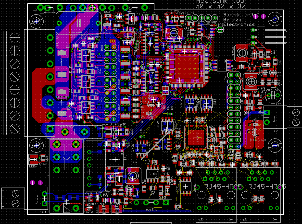
An EtherCat slave controller would fit nicely onto my servo board together with two RJ45 jacks. The EtherCat interface would make the P1 and most of the IO attached to it redundant. The fact that the P2 is located on the high voltage side makes a lot of insulation data couplers necessary. But they are cheap ($0.17 each) and fast (100MBd) theese days. I think the BOM cost is even a bit lower than before.
Yeah! I've convinced the second last "gatekeeper" to let me in. To enable the power stage you have to switch another state machine from "disabled" to "operation enabled" state. But that's too easy, of course. To make it a bit harder you have to go through two intermediate states "ready to switch on" and "switched on" and each of the state changes have to be checked and acknowledged by the drive. And to make it even more interesting those states don't just have linearly enumerated numbers. Bah, how boring. Each state has a special bit pattern and the bit numbers are different for the command and the acknowlege register. Riddle solved, the motor is powered and I can feel it has holding torque.
The last exercise (hopefully) is to find out how to enable motion. I've already found out that there are parameters for contour speed, acceleration and limits for min and max position. They are all set to zero by default so, of course, nothing can move if I don't set them to reasonable values. Then there is a bit in the control register that tells the drive that there is a new position set point. I think I have set them all but the motor still doesn't move.
Is the control mode of torque/velocity/position, and tuning of, already preset? Maybe still have to select to use that preset.
If you are interested, here is a more detailed description of the problem. And yes, I have set the control mode to position profile (PP), at least I hope so.
But I already have a suspiction. I think the drive falls back from fully operational state to the "safe-op" state for some reason (watchdog timeout or some similar reason). The safe-op state is an intermediate state to keep motors or actuators in general quiet during the initialisation phase. Otherwise, if parameters are set one by one there could be unsafe states or jerks. For example when I set gain first and offset second for a control loop then the offset is wrong for the new gain until it's also updated. If I do it the other way round then the gain is wrong for a short time. In safe-op state the outputs and also motion are disabled to avoid this problem. I thought that even powering the motor and holding torque should be forbidden. But that might be a bug or "mis-interpretation" (aka ignorance) of safety laws by the Chinese manufacturers.
I have to monitor state-change events and all of the status and error registers to catch such unexpected state changes.
Hmm, that is a puzzle. Maybe try Profile Torque mode for the most basic control just to see if it will move on command.