Video buffer for p2videodrv.spin2
 ke4pjw
Posts: 1,334
ke4pjw
Posts: 1,334
I am looking to use the DVI output of the p2videodrv.spin2 as a way have a "virtual matrix" display for my Christmas Display. I need to understand how the pixel data is arranged in memory.
Is it RGB? How many bits per pixel, etc. Does the top of the buffer represent top left, bottom left, etc. Is it interlaced, like the first part of the buffer is every other scanline and halfway down the buffer it starts at the top again?
I looked at the source code and kind of understand some of it, but the buffer is a mystery. I suspect this is one of those things that people that deal in this space "just understand", so sorry if this is an elementary question. If there is some kind of application note or webpage you can point me to, it would be appreciated.
As always, thanks in advance.
Comments
There's multiple possible pixel formats. The most useful ones are LUT8 (256 color palette), RGB16 (packed RGB565) and RGB24 (4 bytes per pixel(!) - ignored, blue, green, red).
The order is left-to-right, top-to-bottom, which is the order any normal video display uses, which is why no one specifies it. (interlace modes are whacky with this driver and require exerting some brain power on the skew parameter)
Excellent! Thank you! With RGB24, what is byte#4 used for?
Nothing. It's just there to waste exorbitant amount of memory and make us all upset because the FIFO can't load exactly 3 bytes. Also, it's the first byte. That's the order: dummy, blue, green, red. When used as a long, that's $RRGGBBXX.
(Well, technically it has some control function (for DVI, bit 1 switches TMDS encoder into 30 bit raw character mode), but RGB24 mode ignores this. notably, LUT entries do not.)
Got you! I think I can work with that. Thanks! I now understand what you mean by ignored, blue, green, red.
Seems Ada has already mostly explained it for you while I'm still waking up
The interlaced mode is flexible but its use can be unwieldy. You can use it in two different ways, when enabled.
There is a buffer pointer for each field of the frame indicating where in HUB (or external memory) the display buffer is sourced from.
To configure it you call:
The driver code will alternate rendering from these two buffers per field. If interlacing is disabled you only need to call setSource.
The two ways to use it are:
1) set these buffer sources to use two separate non-overlapping areas of memory. This way you can mess with one buffer fully without affecting the other buffer currently being displayed and you can do block copies etc and just have the driver ping pong between these buffers. Having two separate fields in memory can be good for outputting already interlaced source material like decoded video, or for doing games at 60Hz etc, where you can manage a dedicated memory buffer per field.
2) set the alternate buffer source pointer to be one scanline worth of data after the primary source pointer in memory and also set the skew parameter to be one scanline worth of data in size as the extra offset to be added after a line using setSkew(region, skewAmount). This way the buffers will interleave by one scan line and the driver will take every odd line of the already interlaced frame buffer and render it out in one field, then do the even lines and render it out in the next field, and so on. This is good for outputting already non-interlaced source material like graphics screens from a single frame buffer in the interlaced format.
UPDATE:
Forgot to mention. To enable interlacing on a region you'd also need to OR in the INTERLACED_SRC flag in the given region's flags using setFlags(region, flags)
I need to put that together. I do have some incomplete documentation I am working on, but realize I still need to add good examples for each specific feature before it's ready to include for the next release.
One other thing...in case this helps with your buffer order.
Even though the display buffer usually get rendered from left to right and from top to bottom line order in memory, you can actually configure negative skew amounts to reverse the line order (still left to right but now bottom to top).
At the end of each scan line you would subtract two scan line sizes worth of data which then backs up the internal pointer to the start of the prior scan line in memory for the next scan line to be displayed on screen. You would also set the buffer start to be the beginning of the last scan line in memory.
One thing that can't easily be done is to reverse the render order from right to left. This is due to the high speed P2 block transfers needing to be incremented as well as the streamer only ever incrementing in memory. If it could be set to decrement it could potentially be rendered from right to left. That could be helpful for portable LCD displays which may have to be reversed when held upside down etc.
Yeah, I am looking to do a 200x150 set of pixels. That's about 120K of RAM.
I am guessing the way it works, based on a review of the text driver, there is no full framebuffer? (and how could there be at 800x600)
You can setup a full framebuffer in HUB if it fits with the chosen colour mode bit depth and resolution. If not, you can potentially use external PSRAM if you need to which supports frame buffers up to 1080p in 256 colours.
The regions in text mode do not need a graphics framebuffer, they just render pixels per scan line directly from a much smaller screen buffer array and font array in HUB RAM.
Note that as well as reducing the colours, enabling both pixel and line doubling options can reduce the graphics frame buffer memory requirements further as the driver can for example fill 640x480 screen pixels with 320x240 memory pixels.
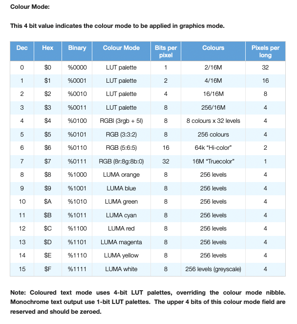
Here are all the colour modes my video driver supports.