

Simple Spooner Robot
 iseries
Posts: 1,547
iseries
Posts: 1,547
Here is a simple winter robot project that is simple to build. I've been wanting to build this for some time now but finally got around to putting it together.
What is needed:
2 - Micro servos continuous rotating
2 - Wheel kits
1 - 3D printed frame
1 - WX ESP8266 board
2 - 18680 batteries in a case.
1 - Custom P2 Board with P2 Edge.
1 - Spork.
Many years ago, I built this project with the P1 using the Parallax Activity Board. This board provided the power output for the servos so it was easy to plug them in a get them running.
The P2 doesn't have an Activity Board or a servo board to drive these servos so that's a problem.
My Custom board has a 1 AMP buck converter on it so driving these little 3v servos is no problem.
My first attempt at designing and printing the frame led much to be desired. The holes are too big for the screws and the height of the blocks were too low to allow placing the batteries under the Custom board.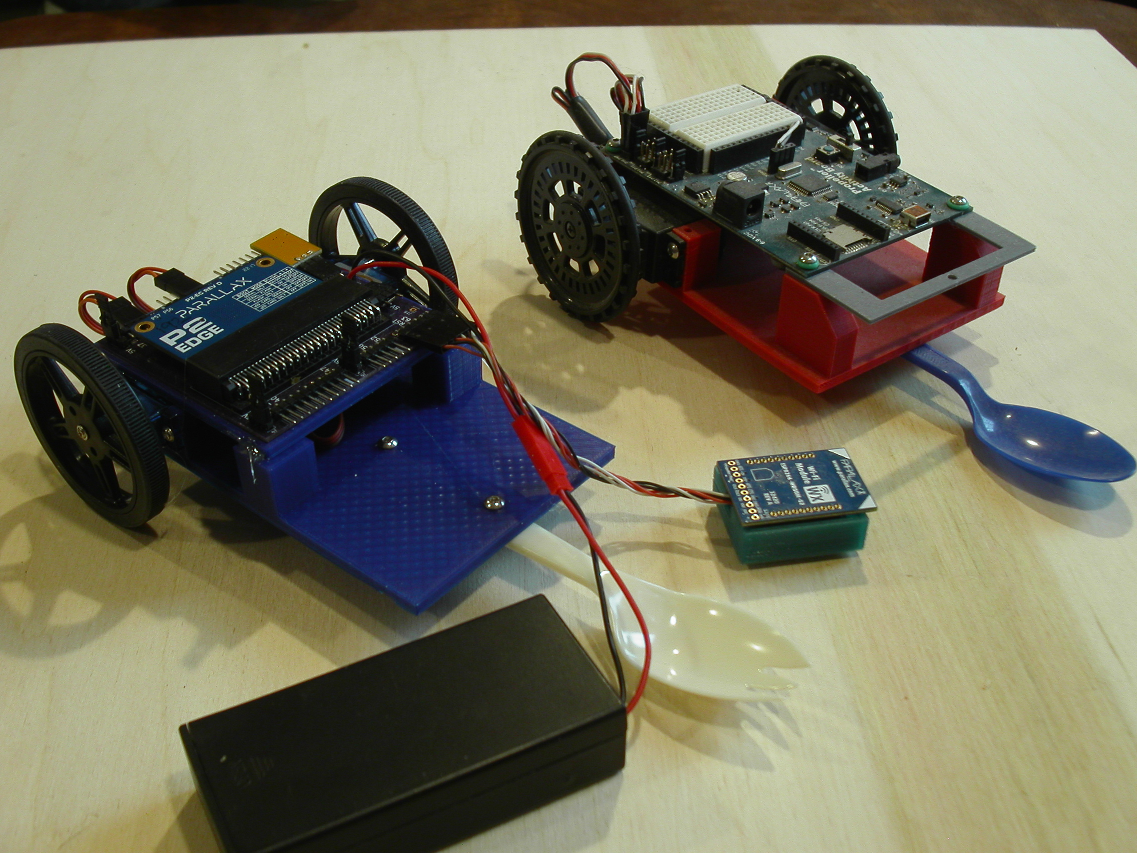
As you can see the previous design had a much higher frame to allow room for the batteries.
The P1 code to drive the servos is much more complicated than that of the P2. Anyway, adding my servo library was simple enough and a simple test program showed that the servos do run nicely.
#include <stdio.h>
#include <propeller.h>
#include "servos.h"

#define Left 20
#define Right 36


int main(int argc, char** argv)
{

    Servo_Enable(Left, 1500, 20000);
    Servo_Enable(Right, 1500, 20000);

    _waitms(5000);

    printf("Starting...\n");

    Servo_Set(Left, 1300);
    Servo_Set(Right, 1700);

    _waitms(5000);

    printf("Stopping\n");

    Servo_Disable(Left);
    Servo_Disable(Right);


    while (1)
    {
        _waitms(1000);
    }
}
Pardon my C code as the SPIN code would be just as simple.
With the WX ESP8266 I am able to download the code to the unit and also later with some more advanced code be able to control it as well.
Mike
Comments
Very cool! Now we just need to see them performing a figure 8.
You've got me wanting to get my 3D printer working again.
Please, pardon my ignorant question but why would you build the same robot with the P2 when you already have done so with the P1 ?
Does the old one lack features or performance you can't add to it ?
@Maciek ,
Good question, the art of building something as a model airplane builder does is make more of what he already has.
The construction is all in the detail. Updated parts and material may lead to new experiences.
They look the same and do the same thing but are very different on the inside.
Frankly, the P2 is way over kill for this project. A P1 would be way cheaper in this case.
Mike
I personally think it's a good idea just as a fun way to learn to program the P2.
I have a variety of P1 robots and only a few of them would benefit from the P2. The P2 has lots of cool features which are absent tin the P1 but the P2 also has a lot more RAM. The increase in RAM is the main reason I'm switching some of my robots from a P1 brain over to a P2 brain.
@iseries & @"Duane Degn"
Thanks, gents. Good news then.
I was probing the other peoples' reasoning for doing much the same things but a bit differently each time to see if I need a psychic treatment without delay or it can be postponed yet another time. Turns out, it can.
I try to rebuild first but it often ends up with another unworthy piece of ...something to be worked upon.
Such a neat idea. Reminds me of a drag racing car.
Are the 3D print files available ?
@VonSzarvas,
Don't know if 3D prints will be of much value to others as its designed for a custom P2 board. I do have a layout for the servo though that may be of interest to others.
Mike
I'm very interested in the remote control part though and ESP8266, and I hope you'll keep this thread going with examples.
I'm with Duane on this. There is no such thing as "overkill" when it comes to educational devices (that's my opinion, of course).
Well done, Mike.
Aah, you shouldn't sell yourself short - I'd imagine they'd have great value to others.
It looks like the red one includes the larger continuous servos rather than the cute mini servos, so the files for that 3D print might be even more useful to most people as a starting point using parts that might be hanging around. As for the custom board fittings (or rather the possible need for an adapter)... an adventurous creator surely wouldn't be held up by that challenge!
Anyway- it's a really cool idea. Would be fun to see them racing about on your YT channel !
This is the sort of thing that could start a new craze.
Fun! Looks like something I'd like to try!
@JonnyMac ,
Funny you should mention that the original unit used a Xbee to transmit codes to the unit for control. It read the position of the pots and send serial data over the paired Xbee to move the motors.
The activity board was all set for the Xbee and was just a matter of pairing them together.
Now with the ESP8266 it gets a little more interesting in that it is attached to my home network and If I paired it with another ESP8266 for the transmitter I could control this bot from anywhere in the house.
Also I like to use LOGO and just send it a program that runs around the room.
Mike
I built a prop remote control for a friend using just an XBee, 3v supply, a switch, a button, and a pot. We setup the XBee in the remote to deal with the analog and digital channels; the remote was actually queried by the prop (which has a P1 inside) to see it it was on and the acquire the channel settings. We had two remotes, so if one died the other could be turned on and take over. All of this used 64-bit addressing.
The Challenge: Send data from one Parallax ESP8266 to another Parallax ESP8266.
This seems like a tricky problem as the units were not really meant to do that.
Here is the setup:
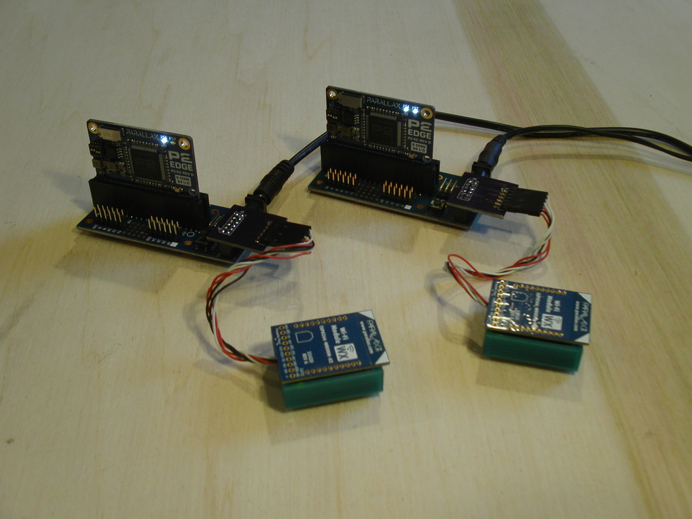
The tricky part was using the units to load the code at the same time. When you load code using the WiFi modules it puts them in transparent mode so no commands will work.
To get them back in command mode you need to use the web interface and change the setting after the code is loaded.
Now how to send the data from one unit to the other. This is very simple in that the units have a telnet port already running and all you need to do is open a connection from one unit to the others telnet port and send your data. The host unit will see it as plain text data and require very little coding to handle that.
The sender on other hand is very complicated. First you need to set the unit in command mode so you can send the setup code.
By using the CONNECT command set to the other units IP address and port 23 which is telnet we can make a connection. Then using the SEND command, we send the information we need to the other unit.
The problem is that the P2 and Flexprop do not provide a full duplex standard IN/OUT function or a way to close these ports so one could open them with a full duplex serial interface.
Well, the P2 is a little more forgiving than the P1 when using smartpins. So you can kind of cheat with how you use those pins for serial communications.
Anyway here is a sample program that did send some data to the other P2.
#include <stdio.h>
#include <propeller.h>
#include "fullduplex.h"


#define JOIN    0xEF
#define CONNECT 0xE4
#define CLOSE   0xE8
#define LISTEN  0xE7
#define REPLY   0xE5
#define POLL    0xEC
#define RECV    0xE9
#define SEND    0xEA
#define CHECK   0xEE
#define SET     0xED
#define PATH    0xEB
#define ARG     0xE6
#define CMD     0xFE
#define UDP     0xDE
#define SLEEP   0xF1

char Buffer[256];
char c;
int i;


int main(int argc, char** argv)
{

    _waitms(5000);
    FD_Init(230400);

    FD_PutStr("Ready?");

    while (FD_Check() == 0)
        _waitms(1000);

    c = FD_Getch();
    FD_Putch(c);
    FD_Putch('\n');

    // Connect to other ESP8266 unit
    FD_Putch(CMD);
    FD_Putch(CONNECT);
    FD_PutStr("101.1.1.208,23\r\n");

    _waitms(5000);

    i = 0;
    while (FD_Check() > 0)
    {
        c = FD_Getch();
        Buffer[i++] = c;
    }

    FD_Putch(CMD);
    FD_Putch(SEND);
    FD_Putch(Buffer[4]);
    FD_PutStr(",13\r");

    _waitms(500);

    FD_PutStr("Hello World\r\n");

    FD_Putch(CMD);
    FD_Putch(CLOSE);
    FD_Putch(Buffer[4]);
    FD_PutStr("\r\n");

    _waitms(500);

    while (FD_Check() > 0)
    {
        c = FD_Getch();
        if (c != CMD)
            FD_Putch(c);
    }


    printf("\r\nDone\n");

    while (1)
    {
        _waitms(1000);
    }
}
As you can see I build a full duplex driver which is needed to capture the results of the commands so you know what handle is used to send the data. In this case I sent "Hello World".
I need to build a ESP8266 driver that puts all these pieces together so it's not so messy.
This shows that it is possible to send serial data between two ESP8266 units.
Mike
I claim dibs on the first P2 robot with remote control using esp8266 to transmit the position of the joystick using a P2.
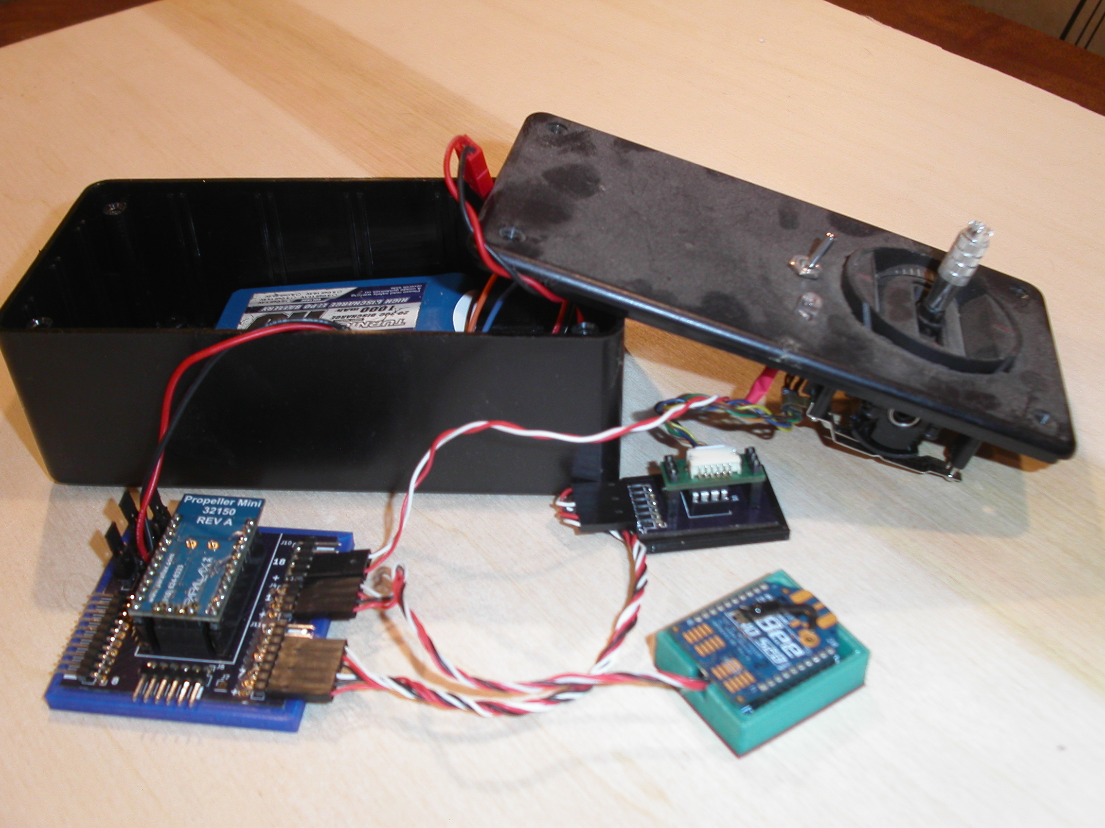
The setup:
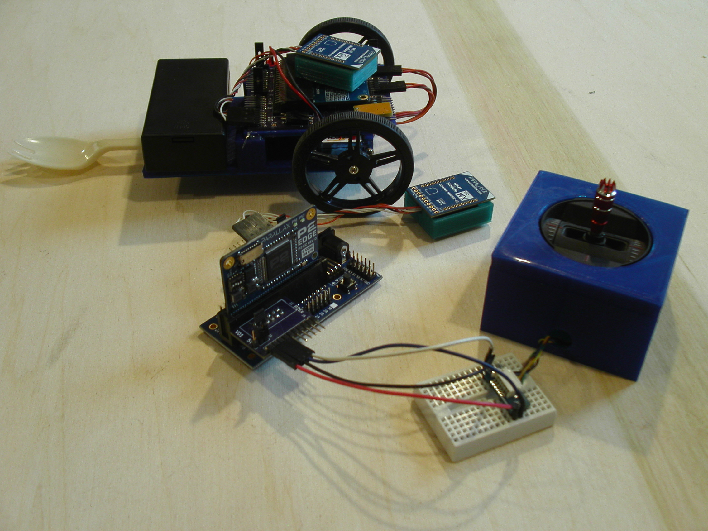
1 - Joystick I was looking for this one but could not find it.
2 - WiFi Units
The P2 using ADC reads the position of the Gimbal and then normalizes it to be a value between 1000 and 2000. It also opens a connection to the other WiFi module using port 23 telnet.
It then sends serial data with the X and Y values normalized as a string "14801480" with a carriage return added to trigger the other P2.
The other P2 uses simple serial receive program that waits for a carriage return and then parses the string into X and Y. Since X is the forward value in this case the Y value is the amount to turn the robot left or right.
Receive Program
#include <stdio.h>
#include <propeller.h>
#include "servos.h"

#define Left 20
#define Right 36

char Buffer[1024];


int main(int argc, char** argv)
{
    int x, y;
    int f;

    Servo_Enable(Left, 1500, 20000);
    Servo_Enable(Right, 1500, 20000);

    _waitms(1000);

    while (1)
    {
        gets(Buffer);

        y = atoi(&Buffer[4]);
        Buffer[4] = 0;
        x = atoi(Buffer);
        f = 1500 - y;

        y = x - f;
        x = x + f;

        Servo_Set(Left, x);
        Servo_Set(Right, y);
        _waitms(20);
    }
}
Gimbal Program
#include <stdio.h>
#include <propeller.h>
#include "esp8266.h"
#include "smartpins.h"

#define XPIN 17
#define YPIN 16
#define RX 1
#define TX 2

char Buffer[1024];


int main(int argc, char** argv)
{
    int i;
    int x, y;

    printf("Ready\n");
    gets(Buffer);

    _pinstart(YPIN, P_ADC | P_ADC_1X, 13, 0);
    _pinstart(XPIN, P_ADC | P_ADC_1X, 13, 0);

    esp8266_Open(RX, TX, 230400);

    i = esp8266_Connect("101.1.1.210", 23);

    if (i < 0)
    {
        printf("Bad handle (%d)\n", i);
        while (1)
            _waitms(1000);
    }

    while (1)
    {
        // Scale values to 1000 - 2000
        x = 1000 * (_rdpin(XPIN) - 7220) / (9875-7220) + 1000;
        y = 1000 * (_rdpin(YPIN) - 7025) / (9875-7025) + 1000;
        sprintf(Buffer, "%d%d\r", x, y);
        esp8266_Send(i, Buffer);
        _waitms(100);
    }
}
I was going to leave the WiFi as the P2 loader on the Gimbal side but timing to put the unit into command mode was a little tricky.
ADC to read the Gimbal though worked rather nicely.
Mike
I'm also trying to add WiFi to my bot...
Don't see any Spin2 examples out there...