

Line following bot using low cost, Arducam, camera module (More or less working already)
 Rayman
Posts: 16,458
Rayman
Posts: 16,458
Want to investigate using a ~$6 camera module to have a robot follow a line...
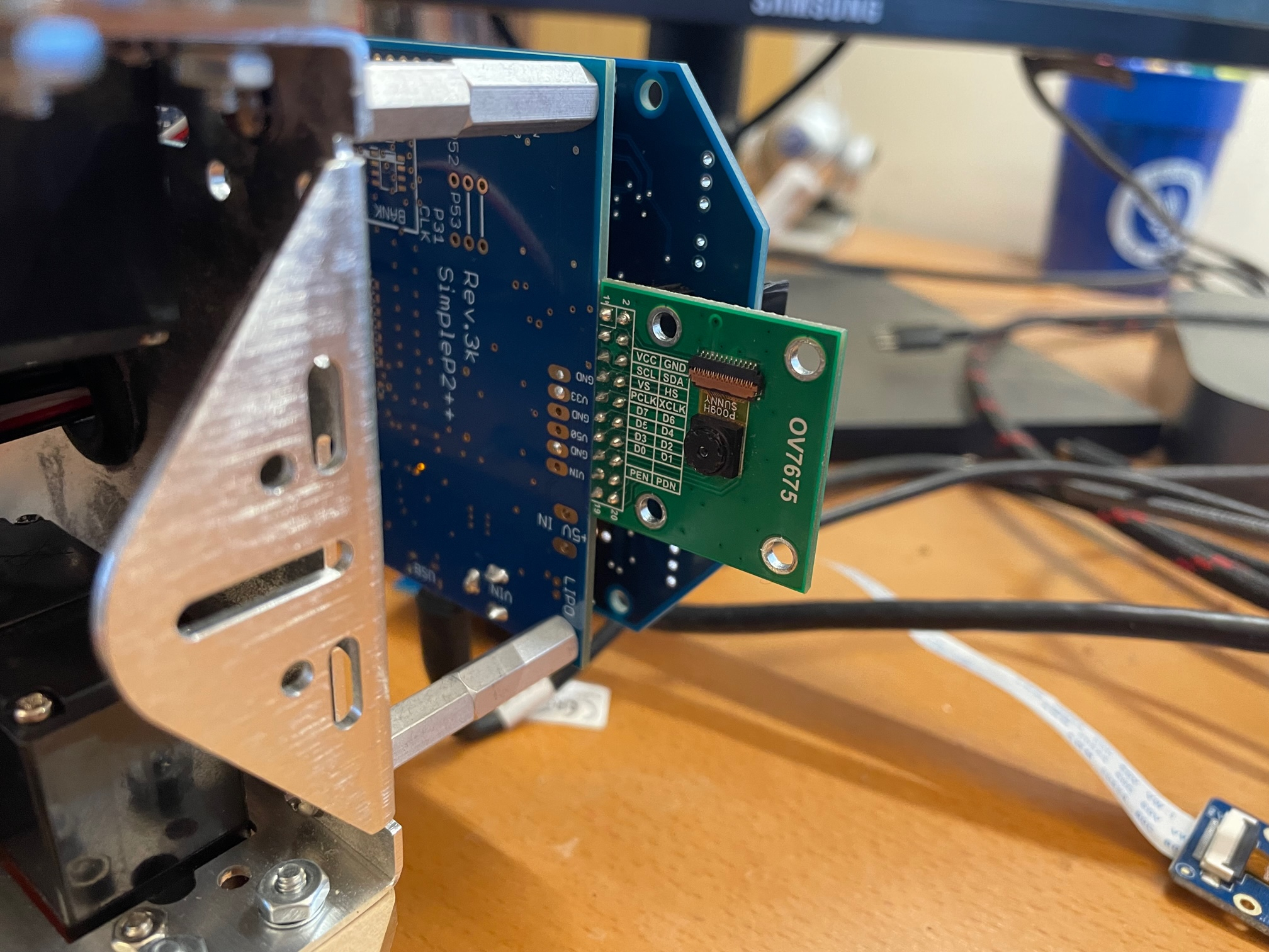
Just finished adapting this Arducam code from C to Spin2.
Works with most recent Prop Tool.
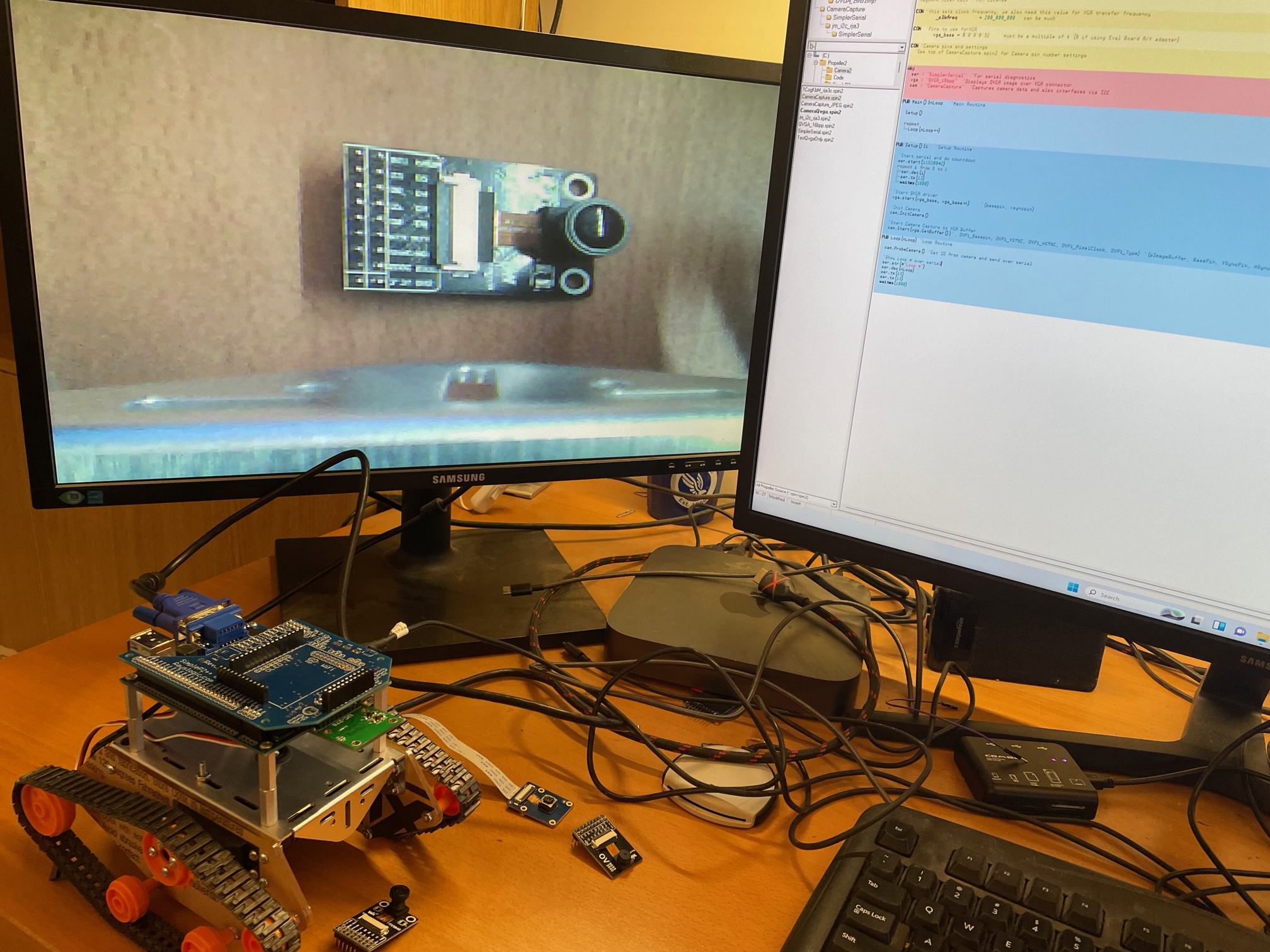
Currently displays QVGA image onto VGA monitor.
Next step is to decimate the image into something more manageable, like 8x8.
Then, can do some simple logic to make it follow a colored line (hopefully).
Or, can use WiFi link to send image to PC and let it figure out what to do and send instructions back to bot...
This place seems to have plenty of these modules:
https://www.uctronics.com/640x480-0-3-mp-mega-pixel-lens-ov7675-cmos-camera-module-with-adapter-board.html
It's the link from Arducam.com:
https://www.arducam.com/product/640x480-0-3-mp-mega-pixel-lens-ov7675-cmos-camera-module-with-adapter-board/

Comments
Can also use camera with other boards using jumpers, or this little adapter...
Arducam also seems to sell a newer version themselves, although hard to find on website:
https://www.arducam.com/product/ov7675-vga-color-20-pin-dvp-camera-module-for-arduino-giga-r1-wifi-board/
Have to be careful with some of the modules out there because some have 0.2 mm pin spacing instead of 0.1" pin spacing. The above looks like 0.1" though. Just ordered two...
The FlexProp C version is in this thread from last year where also jpeg capture from ov2640:
https://forums.parallax.com/discussion/175105/jpeg-image-capture-from-arducam-ov2640-eve2-lcd
Capturing jpeg would be an alternative approach because can relatively easily extract one pixel from every 16x16 pixel square of jpeg.
But, QVGA to something smaller seems easier...
This version can also do OV5640 and OV2640
Tested with modules from WaveShare:
https://www.waveshare.com/ov2640-camera-board.htm
https://www.waveshare.com/ov5640-camera-board-b.htm
Had to increase the drive strength a bit on OV7675 and OV2640 to get perfect display. Probably because my wire length between camera and P2 is a bit longer on robot than it is with P2 Eval board with adapter.
VGA cable isn't so convenient for mobile robot, so switching to the Parallax OLED module.
Fortunately, @ke4pjw posted some code for it, so should be easy transition...
Very neat 👍
I have this note in C version of Arducam code regarding output pixel clock freq from camera:
    //Scope measurements 31Dec22:
    //in QVGA raw mode, pixel clock is 15 MHz
    //In QVGA jpeg mode, pixel clock is 10 MHz, capture data on rising edge
    //In VGA jpeg mode, pixel clock is 20 MHz, capture data on rising edge
    //in SVGA jpeg mode, pixel clock is 15 MHz, captur data on rising edge
    //in XGA jpeg mode, pixel clock is 15 MHz, captur data on rising edge
    //In 1600x1200 jpeg mode, pixel clock is 20 MHz, capture data on rising edge
At 15 MHz pixel clock and P2 at 300 MHz, seems have lots of time to create downscaled output.
Think can have 40 instructions in pixel read loop (as 2 clocks per instruction and two byte pixel clocks per 16-bit pixel.
Right now, looks like have 8 instructions in the pixel read loop:
'Read in horizontal line rep @capture_line,#320 waitse3 'wait rising edge on pixel clock...pclk getbyte1 mov i,ina'b getbyte1a shr i,#0'4 waitse3 getbyte2 mov j,ina'b getbyte2a shr j,#0'4 wfbyte j wfbyte i capture_lineI'm repurposing the IR LED holes to provide white LED lights.
Sanded off the top of the LEDs to provide more uniform lighting.
Brightness seems about right. There is some reflection to deal with from some surfaces, but think will be OK.
This is another case where new P2 assembly commands make things so much easier than on P1...
Just starting to look at taking two bytes and combining into 16-bit RGB value and then separating in RGB bytes for accumulation and decimation.
Getting into RGB bytes is super ease with setbyte and rgbexp commmands:
rep @capture_line,#320 waitse3 'wait rising edge on pixel clock...pclk getbyte1 mov i,ina'b getbyte1a shr i,#0'4 setbyte rgb,i,#0 waitse3 getbyte2 mov j,ina'b getbyte2a shr j,#0'4 wfbyte j wfbyte i setbyte rgb,j,#1 rgbexp rgb capture_lineThink getting close to having it work now...
Using the Parallax OLED to monitor camera output.
Code now compresses QVGA camera buffer into a 10x10 array, shown in the left side of OLED.
Discriminator output is on the right side, uses SAD algorithm to judge if each pixel in 10x10 array is tape or floor.
Red is floor and Green is tape.
Appears to work well enough...
Nice!
To recognise the position of a distinct color blob a good way can be to convert each pixel rgb into hue and brightness. And then calculate the average of positions for all pixels, which have hue in a certain range.
Perhaps this can be done on the fly, you do not need the complete picture in Ram.
Thanks @"Christof Eb." , things to think about....
Robot passed this first test 6 of 6 times now with this code.
Code definitely could be improved...
Right now, just uses the top 10 pixels of the processed 10x10 pixel array.
Will probably be better and faster in the future.
Also, I'm pretty sure it would get stuck at "T" intersection as it is now...
Code is definitely getting big and a bit complex now.
Added in NeoPixel driver to indicate line following status...
Using a pack of colored masking tape for now. Green seems to work better than yellow, but do have some other colors to try...
Might consider having bot do different things when it sees different colored tape in the future...
My daughter thinks it'd be better if one could stick their iPhone into the bot and have it control it... Something to think about...
Thanks Rayman for this! Here is my P2KISS version of this, ready for loading the program. If it works I probably put it in the stingray-shaped robot.
@SteffeD1 Awesome. Thanks for sharing. Your setup looks a lot like mine electrically, so I think it should work with just minor changes to my code...
There are a lot of improvements that can be made to the code though for sure.
One thing that I'm not sure mentioned is that one needs to first take several images of floor and then several images of all tape to use as reference. Maybe that is included in what I posted, I don't remember... Doing the floor is no problem, but making a large square of tape is a pain. Maybe easier way can be found...
I'm using OV2640 Waveshare module, and when I'm running the CameraQvga program it responses Camera ID = FFFF and the vga monitor shows a pink picture. What am I doing wrong?
Make sure the i2c pin assignments are correct … does the camera show up in the i2c bus scan?
Also make sure providing clock, it needs that to work…
I'm happy. Now it's working! Thanks a lot.
Glad to hear it! Congrats.