Archive of ftp.propeller-chip.org ?
Does anyone have a link to / copy of the FTP archive at ftp://ftp.propeller-chip.org?
I'm interested in the PropC3/ top level directory, in case there are only partial archives available.
Does anyone have a link to / copy of the FTP archive at ftp://ftp.propeller-chip.org?
I'm interested in the PropC3/ top level directory, in case there are only partial archives available.
Comments
Acopy can be found here: https://www.mmnt.net/db/0/0/ftp.propeller-chip.com
This is only an index — when I try to download any of the files it just links to ftp://ftp.propeller-chip.org which does not resolve.
I got some of the C3 files downloaded. What specifically are you looking for?
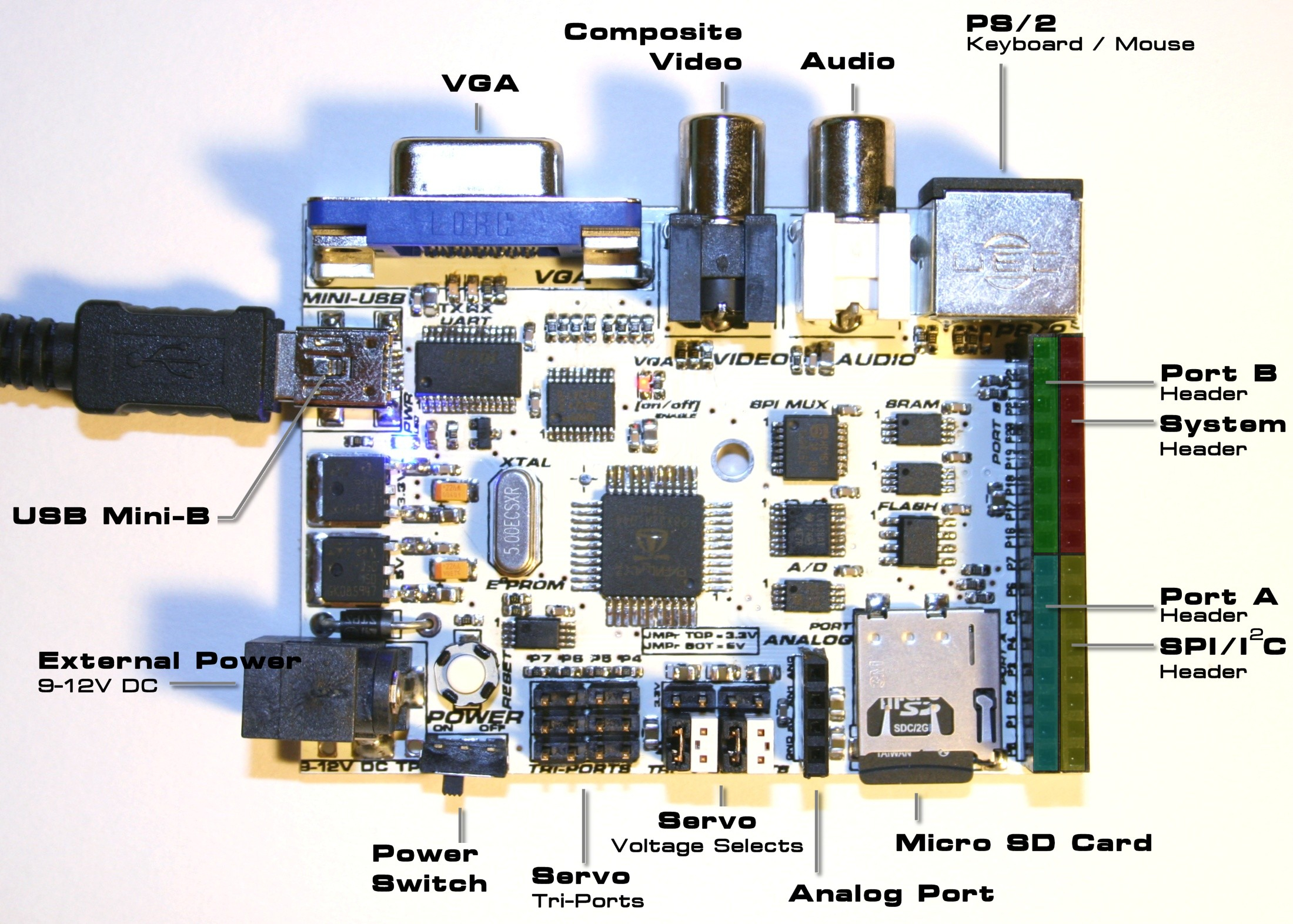
prop_c3_annotated_01.jpg :


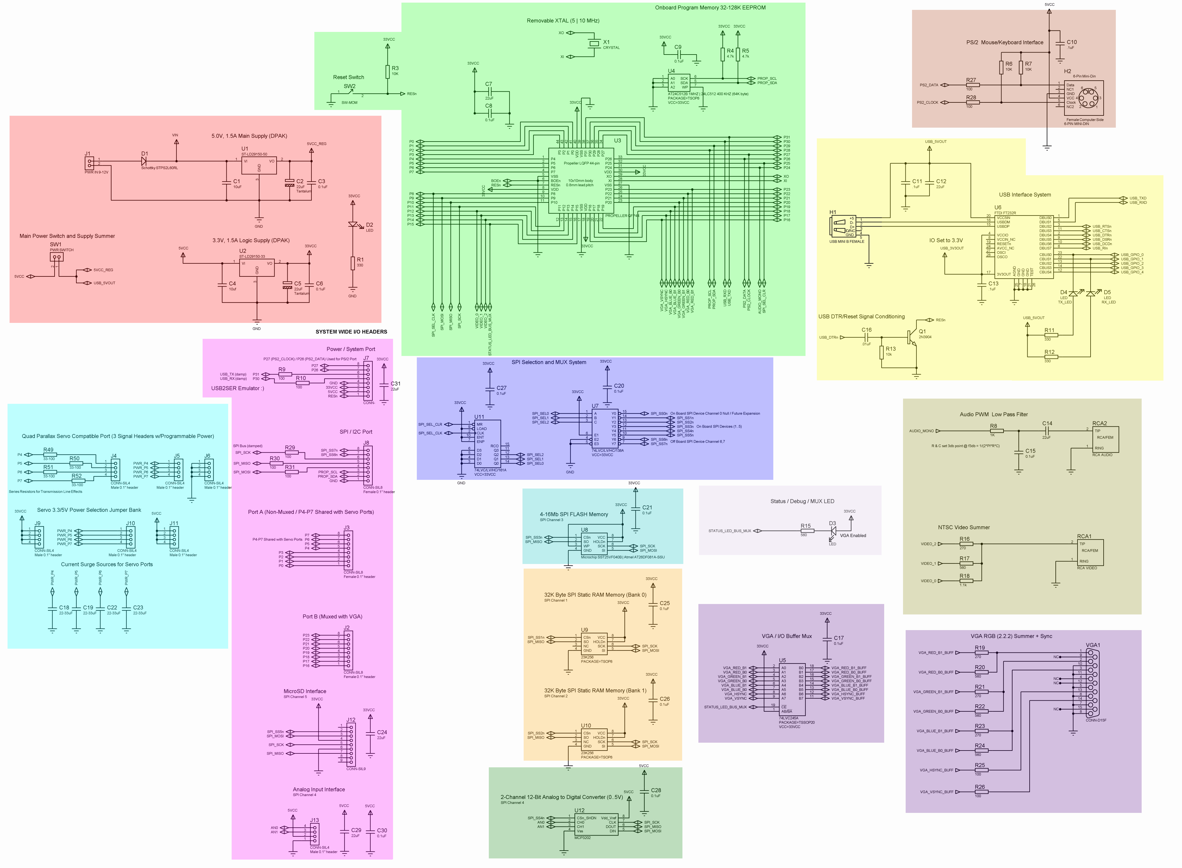
prop_c3_rev_a_lrg_colored_01.png :
Do you mean you downloaded the files back when the FTP server was online? Or are you able to download them from the mmnt archive?
In the latter case, what URL does it end up downloading them from?
Downloaded back in the day. So the selection of files on offer is somewhat limited to what I was interested in (mostly the schematic seen above and some of the program code). Maybe if I boot up an older computer I might find some more, if it's urgent or something.
Not urgent. I was interested in seeing if I could make a copy of a C3 board based on the PCB files.
I assume that to do so I would need:
PropC3\Designs\Schematics
    C3_Proto_Add_On_Dim_Gerbers.zip
    prop_c3_rev_a_bot_copper.pdf
    prop_c3_rev_a_top_copper.pdf
Thanks for the circuit diagram; it's a lot higher resolution that the one included in the Unleasing the Propeller C3 PDF (linked here for anyone else trying to do something similar).
Hmm, I don't think I have those. Do you have a particular reason to clone a C3? It's somewhat of an odd design...
I'm interested in the C3 as a "feature complete" devboard — VGA, Ethernet, audio, mouse/keyboard, ADC, etc.
I was thinking of making a custom PCB but with the C3: (i) I don't have to design the PCB myself and (ii) there is sample code available (although that was also on that FTP server).
oops sorry did not try to download any of the files: some can be found here https://www.ic0nstrux.com/propc3
@rosco_pc is right, there appears to be a full archive here: http://www.ic0nstrux.com/download/propc3/propc3_demo_software.zip
Yeah that makes sense (though the C3 doesn't have any ethernet, where did that come from?). Though building a PCB for a P1 is pretty easy, it doesn't need much special consideration. The C3 is more complex than it really needs to be by account of doing a lot of things at once and even there the schematic fits on a single sheet.
Also note that the C3 schematic has the old and wrong VGA circuit, correct one looks like this:

That's good, Vivaldi didn't want to download the file so I thought it was dead, but it works in Firefox. Good find.
Ah, indeed there is no Ethernet. I kind of just assumed that the C3 was the "do-everything" board.
I have seen a few variations of the VGA-resistor circuit from different devboards. At some stage I will have a look through the example code to see if it makes any assumptions about how that circuitry is set up.
Thanks for the help guys.
The only thing the software cares about is that the pins are mapped to a byte aligned port (i.e. starting on P0, P8, P16 or P24) and in this order: VSync, HSync, Blue LSB, Blue MSB, Green LSB, Green MSB, Red LSB, Red MSB. The alignment is a hardware requirement, but the order is convention. The actual issue is the particular values and design of the DAC resistors leading to degraded display. The one I posted should have proper termination and color levels.