

How to Connect P1 to a Step Motor - a Very Basic Setup.
 Christof Eb.
Posts: 1,598
Christof Eb.
Posts: 1,598
Hi,
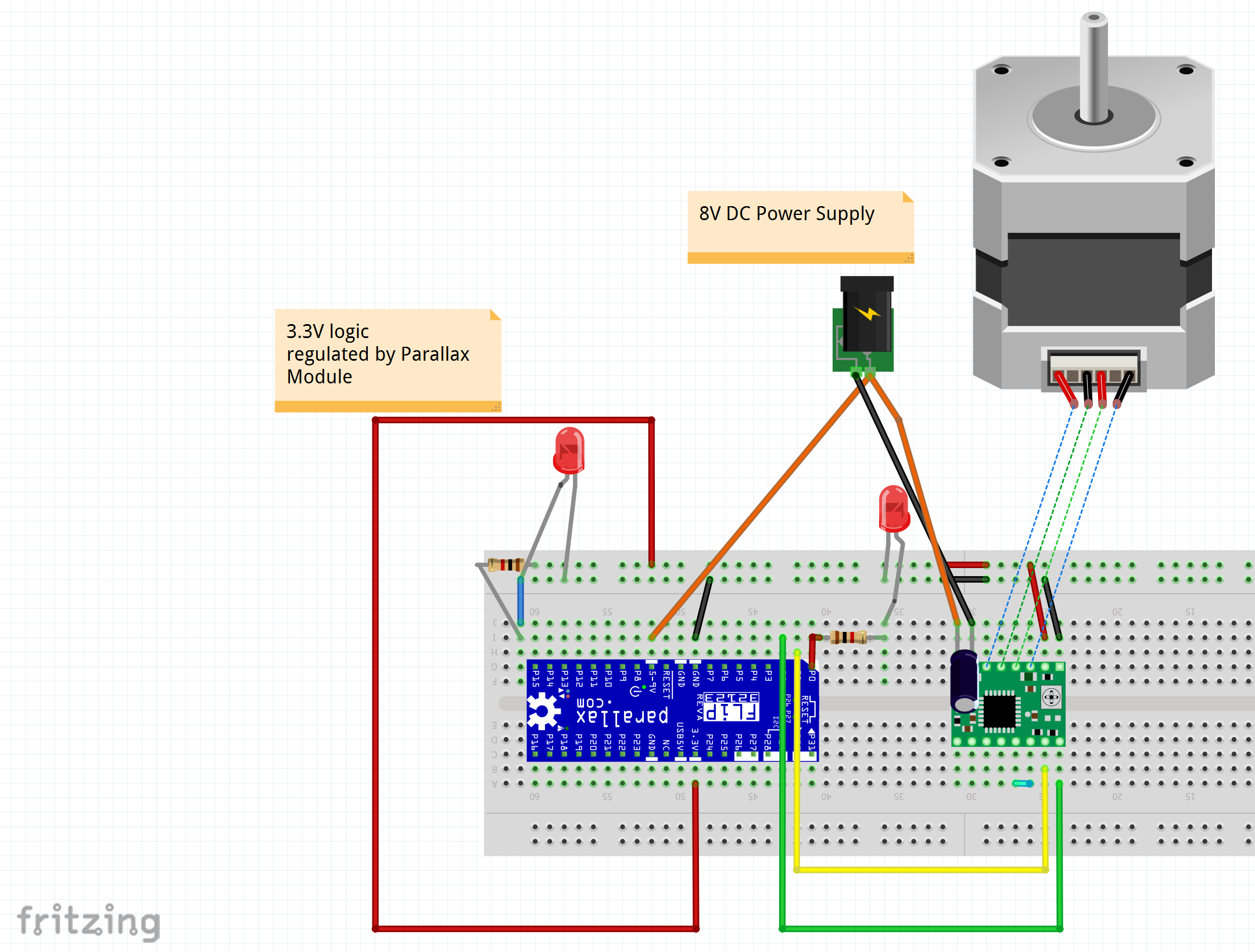
this is a very pure and simple basic example how to connect a bipolar step motor via a A4988 driver module to a P1 and let it spin.
We use a A4988 driver https://www.parallax.com/product/a4988-stepper-motor-driver-carrier-board-black-edition/
Please note, that this module helps in multiple ways:
- Provides the bridge driver to drive the motor's winding currents
- Limits the winding currents
- Is compatible with the 3.3V logic level of the Propeller chip
- Can do microstepping for smooth running
We use a unipolar Polulu Step Motor: https://www.pololu.com/file/0J685/SY42STH47-1206A.pdf
I use the now obsolete P1 Propstick, similar to the Flip module. https://www.mouser.com/datasheet/2/321/32210-PropStick-USB-1.2-370434.pdf
The pins, which are used here are the same, you would use on the actual flip module.
We use a Power supply of 8V, connected to the inputs of the A4988 and also to the PropStick. There is a 1000uF Cap at the power input of the A4988 module. The power supply must provide regulated 8V DC and be able to support enough current for both the motor and the propeller module.
3.3V and GND are connected to the rails of the breadboard, for both the PropStick module and the A4988. There is a regulator onboard the Propeller module which provides 3.3V from the 8V input to this module.
There is a LED with resistor to be sure to have 3.3V power.
P0 drives a LED with resistor, to know that there is something going on.
P1 yellow drives the Step input of the A4988
P2 green drives the Dir(ection) input of the A4988
Enable and MS1, MS2, MS3 are left open here, which has the motor enabled and use full step mode.
These are the connections of the A4988 module: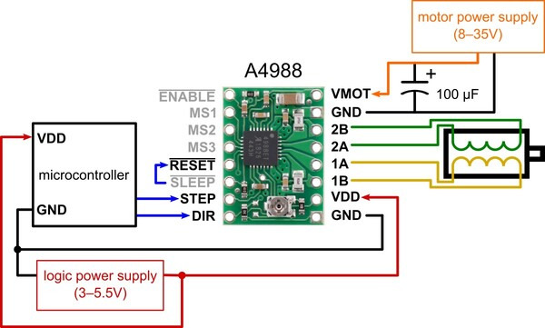
These are the connections of the windings of the motor: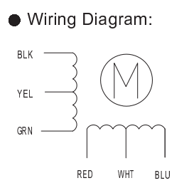
As we are using bipolar mode, we use:
red+blue for winding 1
green+black for winding 2
I have set the motor current potentiometer using the current display of my bench supply to a low current, so I have a total current of 8V 0.2A, which is OK for this test. At the Parallax site there is a link, how to set the optimum motor current.
This is the complete setup: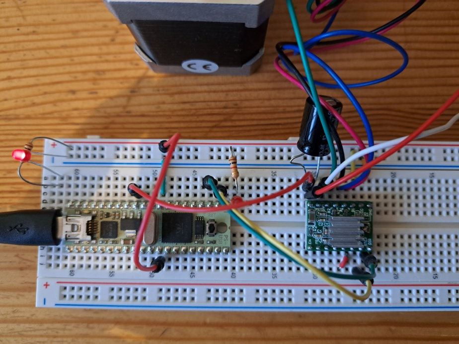
On the top, right hand side, the red and white wires come from the 8V power supply.
This is the program, which toggles P0 and P1 in parallel.
'' StepperLedTestP0A.spin
'' From
''This code example is from Propeller Education Kit Labs: Fundamentals, v1.2.
''A .pdf copy of the book is available from www.parallax.com, and also through
''the Propeller Tool software's Help menu (v1.2.6 or newer).
''
''File: PushbuttonLedTest.spin
''Test program for the Propeller Education Lab "PE Platform Setup"

CON

  _clkmode        = xtal1 + pll16x           ' Feedback and PLL multiplier
  _xinfreq        = 5_000_000                ' External oscillator = 5 MHz

  LEDs_START      = 0                        ' Start of I/O pin group for on/off signals
  LEDs_END        = 1                       ' End of I/O pin group for on/off signals
  DIRECTION       = 2


PUB ButtonBlinkSpeed                         ' Main method

  '' Sends on/off (3.3 V / 0 V) signals at approximately 2 Hz.

  dira[LEDs_START..LEDs_END]~~               ' Set entire pin group to output

  dira[DIRECTION]~~
  outa[DIRECTION]~~

  repeat                                     ' Endless loop

    ! outa[LEDs_START..LEDs_END]             ' Change the state of pin group

      waitcnt(clkfreq / 4 + cnt)             ' Wait 1/4 second -> 2 Hz
The schematic and the picture of the setup: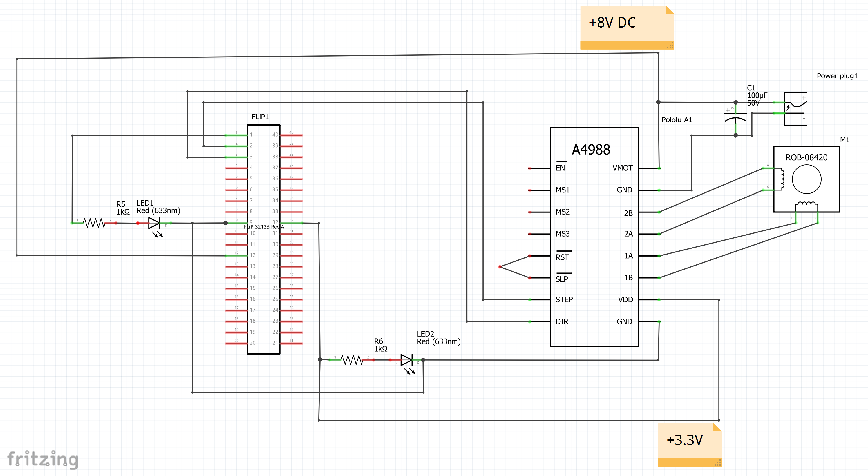
Something missing, understandable?
Have fun, Christof
Comments
Christof,
Thanks for posting this very well written and useful primer on driving a stepper motor from a Prop.
I had no need for a stepper motor driver in my current project wishlist, but I might change that after reading your post - it is too good to pass by!
Christof Eb,
You should provide a full schematic of your Propeller setup for the newbies who may come across this post.
Hi, as this is a good idea, I introduced the schematic into post #1.
@"Christof Eb."
Hey and hello.
I am using this device in a robot arm: https://blog.arduino.cc/2020/09/16/kauda-is-a-low-cost-highly-efficient-robotic-arm/
I have an interesting issue. When I engage the steppers they somehow loose power. Power supply is is 12 30 amp which is more than enough. The steppers slip after a short while. Code is a simple toggle and pin up or down for direction.
pub axis_1_up
    {{AXIS 1}}
  outa[0]:=1 'stEP      'STEP
  outa[1]:=1  'step     'DIRECTION
   ' PauseMSec(1000)

     {{axis 1}}
  outa[0]:=0
  waitcnt(clkfreq/200+cnt)
  outa[1] :=0   'DIRECTION
   waitcnt(clkfreq/200+cnt)
When I tested the arm base all good. Added the lower arm axis 1 all good. Added axis 2 which has a stepper and a servo, it appears that the weight and balance is out. The dual steppers will fail either completely or intermittantly and the arm falls.
When I energise the steppers at rest but in an up position they as expected hold position.
Any suggestions?
Question does the a4988 hold current on the last step? Is this my issue that the a4988 cannot hold constant current unless there is some way to update it?
Thanks
Martin
@"Christof Eb."
Total accident I think I found the issue. HEAT. Will update.
Thanks for your time.