

Loadp2, P2ESflashloader and custom board (50MHz)
 ManAtWork
Posts: 2,369
ManAtWork
Posts: 2,369
I'm still struggeling how to configure VSC to flash my board. I don't use a crystal connected directly to the P2 but use the master clock of the ethernet MAC to drive XIN. It's 50MHz and my code runs fine with theese settings:
CON
  _clkfreq    = 200_000_000
  _xinfreq    = 50_000_000
I can successfully load the binary to RAM with a slightly modified json file.
      "label": "downloadP2",
      "type": "shell",
      "windows": {
        "command": "loadp2.exe",
        "args": ["-b${config:baudRate}", "${config:topLevel}.binary", "-t"]
      },
where baudRate = 2000000. But I have no luck with the flash loader.
      "label": "flashP2",
      "type": "shell",
      "windows": {
        "command": "loadp2.exe",
        "args": ["-b230400", "'@0=${env:FlexPropPath}/../board/P2ES_flashloader.bin,@8000+${config:topLevel}.binary'", "-t", "-k"]
I tried different baud rates but I always get garbled characters at the terminal and the flosh is not programmed. I can program a KISS board with the same settings. It also shows garbled text but the flash is written correctly. Could it be that the flash loader uses an auto baud method to adjust the speed so it can adapt to the slight off frequency? (25 vs 20MHz) But 50 Mhz are too much?
Do I have to set the clock mode explicitly? Where can I find documentation about how the flash loading sequence works? Is the flash loader used only once for downloading the binary into the flash chip? Or does it remain in the flash chip and acts as a two stage loader which reads out the flash ROM and copies it to RAM?
Comments
@ManAtWork : I think you'll have to recompile the P2ES_flashloader.bin file for your custom board, as it has the clock frequency built into it. The sources are in the same directory as the binary. It does not try to do any autobaud detection, and indeed its only I/O is to report status: the actual binary it flashes is written into HUB memory at $8000 by loadp2. And the flash loader is used only once, it does not install any kind of two stage loader.
A better solution would be to modify loadp2 so that it can program the flash directly, without a helper program. I am available to do that kind of work if you (or anyone else) would be interested in sponsoring it.
That's an old piece of code. I've more recently written a crystal frequency extraction routine that could be incorporated.
Then there is also Chip's programmer source code. It is very simple, uses RCFAST. Adapting it for Loadp2 and Flexprop seems a reasonable idea.
Ah, OK, that explains why it still works with the slightly off frequency of the KISS board (25MHz) but the status message isn't displayed correctly.
Yes, ideally there should be no requirement to patch or parametrize anything external. I like the way Propeller Tool does it. Simply press F10 or F11 and the IDE takes care of everything else.
Yes, good idea. I just like to wait a little bit until I have gathered a bit more experience with the flash file system. My ultimate goal is to make a bootloader that looks for a file in the flash file system and then loads it. The problem is not the loader but the process of updating the file. As soon as this can be done by the customer in the field it has to be fool proof but at the same time as simple as possible.
I've made a bootloader and an updating mechanism that works over ethernet for the P1. Although it's designed to be protected against power failures or disconnect during the update many customers still manage to screw it up and end up with a non-functional device which they have to return for re-programming. The updater needs some way of verifying that the software update is compatible with the target device.
I agree. Any loader software should be able to run on any board with any crystal frequency, if possible. RCFAST always works. Unfortunatelly, there is no way to compare the XIN frequency against RCFAST to do some sort of auto-PLL thing. But 20MHz should be enough to load 512kB out of the SPI flash in a about second.
From Chip's "flash_loader.spin2". It operates at sysclock/2 so about 12 Mb/s.
@evanh You're the walking data base! Parallax should hire you to write the P2 documentation.")
Aargh, I should have looked again at the code. In fact there is a small stub loader installed. I forgot that the boot ROM only loads $400 bytes from SPI, and requires that those pass a checksum. So for most practical purposes a two stage loader is required. I was thinking of "two stage loader" as including a file system, which of course is not required.
Thanks, @ersmith, I'll try to get it to work somehow by changing the PLL & clock settings in the P2ES_flashloader.
Again, is there some documentation about the whole boot process? The silicon docs only say "needs more editing"... Do I really have to reverse engineer the source code? I'd like to know how it was supposed to work and what is possible and what not before I decide how to implement a new bootloader.
Hehe, wow, it was written before Spin2 came along. There is no system constants.
About two-thirds down the "P2ES_flashloader.spin2" listing is a bunch of defined constants. All you should need to do is change
XTALFREQ = 20_000_000toXTALFREQ = 50_000_000. And maybe alsoXOSC = %10toXOSC = %01assuming you are using a buffered oscillator module in place of a crystal.Thanks, that works.") The flash is programmed correctly and I can see the messages during flash programming:
The flash is programmed correctly and I can see the messages during flash programming:
However, when the P2 boots from flash there are still some garbled characters. As the pattern looks somehow regular I don't think it's the TX pin just floating.
o©®©®╗ o © ╣ 8 ╣ ╗ G ▒ ■ ¶ â ■ │ í ¶ È Ò ¿ ║ { ¬ ê o ;The boot loader doesn't emit any messages. It just blindly sequences the EEPROM pins to load the main code, clears the pins, reverts back to RCFAST then COGINITs whatever was loaded.
It would be your code doing the serial port work. Maybe just a mismatch in baud.
There is very little documentation that I know of about the boot process. There are a few threads on the forums (most of them very old) and the source code for the boot rom itself .
.
Ah yes, you're right. I had to change the download baud rate to 230400 because the P2ES_flashloader is hardcoded to that. I've changed that to 2_000_000 and now it's
Ok, I think we have to ask the master himself on the next live forum...
Is there a specific question?
Is this the whole boot ROM?
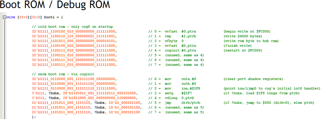
I don't see it reading the SPI chip.
That's the hardwired instructions for copying the internal ROM memory into hubRAM.
The "cold boot" is the first step after a reset. There's a special initial state that cog 0 is in after a reset. The REP'd
WFBYTE 0reads from a port, at register address 0, that consecutively supplies bytes from the internal ROM.Once the ROM is copied into hubRAM the
COGINITthen runs it.The file containing the pasm source code of the ROM was provided in the FPGA zip files back during Prop2 silicon development ... v33k was the final one that got frozen in the real silicon.
Ok, I see. Next questions...
1. Where is the source of the internal ROM and
2. where is the source of Chips flash loader?
flash_loader.spin2 is in Pnut zip files.
Ok, thanks, found it. As always with Chips code he uses self-modifying code and reuses the first instructions as scratch space... But it's well documented so I should understand it. Now, I have some homework and come back tomorrow with the next questions.
 ")