Inductive charging on cylindrical axis?
 JBWolf
Posts: 405
JBWolf
Posts: 405
I need to charge two 21700 batteries in parallel (4.2v 5a each) without a physical connector.
They are contained in a non-conductive cylinder which is 32mm in dia, but I was hoping to charge around the diameter rather than using the flat ends if at all possible.
Basic analogy: Small straw with wire coiled around it (receiving coil), slid inside of a larger straw with wire coiled around it (transmitting coil).
The batteries will be permanently sealed inside, and I do have an empty area of the cylinder which would be perfect for a charging coil to slide over.
Every system I have seen involves two flat coils with their faces brought as close to each other as possible.
I can get the faces equally close on the two cylinders.... but is it possible to use two cylinders overlapping?
Seems to me the EM field would run through vertical coils same as it does on lateral coils?... I dunno
Comments
A drawing (a hand made sketch) of your idea would surely help. My imagination runs wild sometimes and here I can see no room for guessing. The answer depends on what material of the battery (cell) enclosures and how physically located are the elements in relation to each other.
Imagine two batteries inside a PVC tube... the batteries do not take up the entire length of the tube, there is 3" of tubing below the batteries with nothing inside (hollow).
I want to wrap a receiving induction coil around the outside of that lower tube section (the hollow section of tubing 3" below the batteries).... then be able to slide a slightly larger diameter tube over that to charge the batteries.
Relative coil distance will be minimal, approximately 3-5mm... but I might be able to cut that down to 2-4mm.
The actual housings will be made from wood, cnc/lathe machined to desired sizes, sealed in epoxy
Yes, that will work. It'll work a heap better if you have a rod of ferrite inside the tubed coil as well. And may as well have the inner coil inside the tube too. A lot easier to seal it all that way.
Or, if more mechanical strength is desired, go with an iron core into a reinforced neck between battery and coil.
hmmm, I may be able to do a ferrite core, iron will be too heavy though.
Inner coil?
I need a sealed system, the charging coil will be physically connected to a 120v main... cannot integrate the two, there can be no connector on the tube containing the batteries.
I would just purchase a pre-made induction charging system if flat coils are all i need.
But since flat ones wont do, where should I start on this one?
Or can I use the same circuits and simply change the axis of the coils by re-spooling them?
Is it really that easy? Simply match the wire turn ratio?
Even small air gaps introduce a large reluctance into the magnetic circuit
I'd suggest starting with the standard flat planar coils, but bend their copper to conform with your 32mm diameter (bit like a 'pringle' chip). Yes this introduces an alignment angle requirement, but perhaps some well placed magnets can help assist getting the alignment angle right (like newer iphones do with their wireless car chargers etc)
You're building a transformer. Treat it as such.
The pancake coils are a huge compromise when compared to a traditional winding. Stick with your first idea of wrapping an outer winding over an inner winding. Adding the ferrite core just amplifies the strength of coupling a whole lot more than not having it.
Yes, the ferrite goes inside the inner coil. Importantly it goes inside of both coils.
Agreed. As far as a concept goes, it can be made to work. Now the real engineering followed by a POC must go into working out the details if it is feasible in real life (I can imagine a bunch of constraints that need to be met) but it certainly is worth a try.
I would buy those planar wireless transmitter and receiver set from amazon, then unwind those coils and rewind each one over your inner and outer tubes. A ferrite rod would help. But you could try it without first.
I can possibly place a core inside the receiving coil, but I dont see how a second core would be possible since both cores would need to occupy the same physical space.
wouldnt both coils fields be attracted to a single core anyways since it is in the center of the EM field?
Maybe we have different ideas on the coil placements... the transmitting coil (outer) I believe should completely overlap the receiving coil (inner).
It would be very close to being a bifilar coil
This is exactly what I am thinking of... the distance between the two coils would be much closer, and windings would be much tighter... but its a perfect illustration.
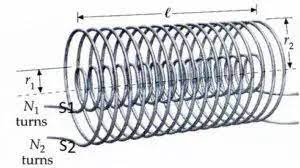
Inner coil is receiving and connected to batteries to be charged, outer coil is transmitting and powered through the control circuit run off 120v
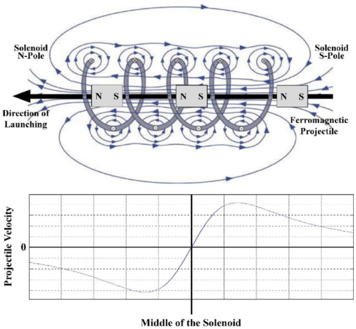
BTW: This is an illustration of a solenoid. I definitely dont want it to have that effect (physical force)
I'm guessing you had in mind this?:
This is not what I want to do... it would require extra material and machining which is exactly what I want to avoid.
I simply cannot find any examples beyond solenoids of using such a system.
It seems to me they are identical though and the EM field passes the exact same way, possibly more efficiently.
But... Transformers always have two coils separated by a distance which from what I can tell is primarily to avoid arcing and heat.
Why are they not overlapping, unless it simply is applicable to high power system with heat and arcing in mind.
But then, I have taken apart small walwart transformers and sure enough, they use the block coil system to space them apart.
I'm so confused as to why there is like 0 information on why not overlap coils like a solenoid does for induction charging.
http://tutorial-hub.blogspot.com/2009/01/how-does-transformer-work.html
Unless using two overlapping cores creates two separate fields that fight each other?
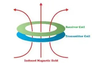
Here is the field diagram of a normal induction system:
You don't need a lot of "coil" and in fact a resonant driver circuit might be what you really want rather than going full bore with 120 VAC on the primary
Video example:
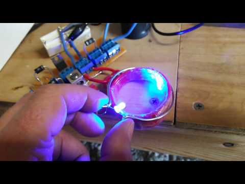
The above circuit in the video started out as a typical ZVS flyback driver. With some modification it makes it more like a CMOS version of a Emitter coupled LC oscillator. Through experimentation it turns out you don't need a center tapped coil (Makes life a little easier), and the V+ can go to either side of the LC coil in series with the 47uH to 200uH inrush current coil. (I think I used 100uH coil). I also found that a series diode on the input supply was an improvement. I omitted the Zener diodes, and just made sure I didn't go over 15V.
For Reference: Google "ZVS driver circuit"
Oh i am absolutely not even considering raw connecting 120vac to the charging coil... i simply mean that is where the general source power comes from (before step-down and rectification to DC).
I want to start with a matching pair of pre-made inductive recharging circuits including protections, definitely with a thermistor... (as batt capacity drops, charge circuit doesnt know and keeps trying to reach 100% resulting in tons of heat and without a thermistor, well this is why there are so many videos of chinese lion batts exploding).
I need to recharge a 4.2v Lion batt, so instead of relearning the wheel, I want to simply modify the coils of a pre-made inductive charging circuit... if that works.
Just wasnt sure if its possible to change the axis... If I have to re-spool the coils, no problem, as long as it will work.
What worries me are the eddy currents around each wire... so theres an electron flux running through the center of the coil, but theres also flux running around the wire itself.
For power delivery, overlapping will be more lossy because the outer winding is further away from the ferrite core. The other downside of your approach is a rod ferrite core is not closed. Which means half the magnetic path is through the air still. It'll still be better than an all-air core though.
Sorry I'm not giving exact information. Sadly this is not my forte.
Seems reasonable. Buy a ready made one then rewind it around a ferrite rod.
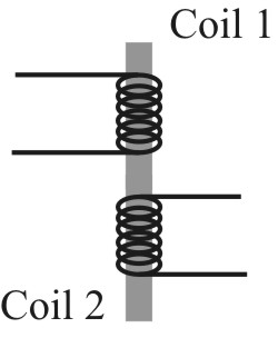
Think I finally found it... its was hard to find, but in some of the 'mutual inductance' teachings they include exactly what I'm looking for.
I have only glanced over it so far, but it looks pretty much exactly the same math as a transformer.
http://electron6.phys.utk.edu/PhysicsProblems/E&M/4-Quasi-static/inductance.html
https://phys.libretexts.org/Bookshelves/University_Physics/Book%3A_University_Physics_%28OpenStax%29/Book%3A_University_Physics_II_-Thermodynamics_Electricity_and_Magnetism%28OpenStax%29/14%3A_Inductance/14.02%3A_Mutual_Inductance
I think changing from stacked horizontal coils to axial overlapping coils works the same.... yet to be proven
will keep posted
You need to be wary of the metal battery case acting as a shorted-turn.
Toothbrush chargers are end of cylinder coupling, so they should give you good examples.
Partial ferrites can help steer the magnetic field coupling.
The toothbrush method is the best example, had one as a kid and wondered how that worked. I remember it had a rod in the base that fit in the end of the electric toothbrush.
Like this
I made absolutely sure that the coil area has no batteries/conductives whatsoever in the vicinity... so we can exclude anything except the coils themselves.
Oh my, I had not considered that method, my toothbrush has a flat bottom, assumed they all used two coils stacked.... like wireless cellphone chargers.
Didnt think about a U-shaped electromagnet, very interesting.
What my new concern is that the 'coil over coil' method does act like a solenoid, exactly the same as a speaker.
When an electron flow is introduced to one coil, it is induced in the other... but when they are nested inside each other (like a speaker/solenoid), the eddy currents oppose each other and produce motion.
Apparently that is the foundation of a railgun as well... think, 'back to the future' speaker maxed out, it blows the woofer (coil) across the room.
I'm hoping that trying to charge a 4.2vdc batt wont have enough jolt to deal with it popping out of the transmitting coik... I wonder if these inductive charging circuits can use a hall sensor or something and slowly ramp-up the transmitting coil to avoid exactly this... or maybe its so low power that there simply isnt enough to worry about it acting like a solenoid. My lawnmower uses a solenoid based EM clutch to engage the blades... one time the coil wire enamel wore through and shorted out, melting all wire shielding and even the pull knob itself. otherwise it pulls the clutch plates together and engages the belt drive
Quick list:
Even unglued, higher frequency, think 100 kHz, will be extremely small mechanical movement because of such high frequency.
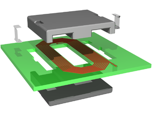
I guess the below image could be done as two flat coils with a small air-gap between the top and bottom cores. One half in the toothbrush and other half in the charger. Then it becomes a flattened transformer with pretty good coupling.