

Stepper motor driver for telescope mount
 bbrien
Posts: 603
bbrien
Posts: 603
I have tried many different drivers for my mount but none seem to work except the Ramsey SMD1 which uses a MC3479 chip which is no longer available. I use a clock line and a directional signal (logic 1 or 0). frequency of clock line ranges from 8 to 130 Hz. I have downloaded several schematics which don't work to well. they all use dual H Bridges in the output stage. One works to some extent . It runs for several seconds then stops pulsing and runs at full speed. I am using two motors from an Arduino robot instead of one stepper.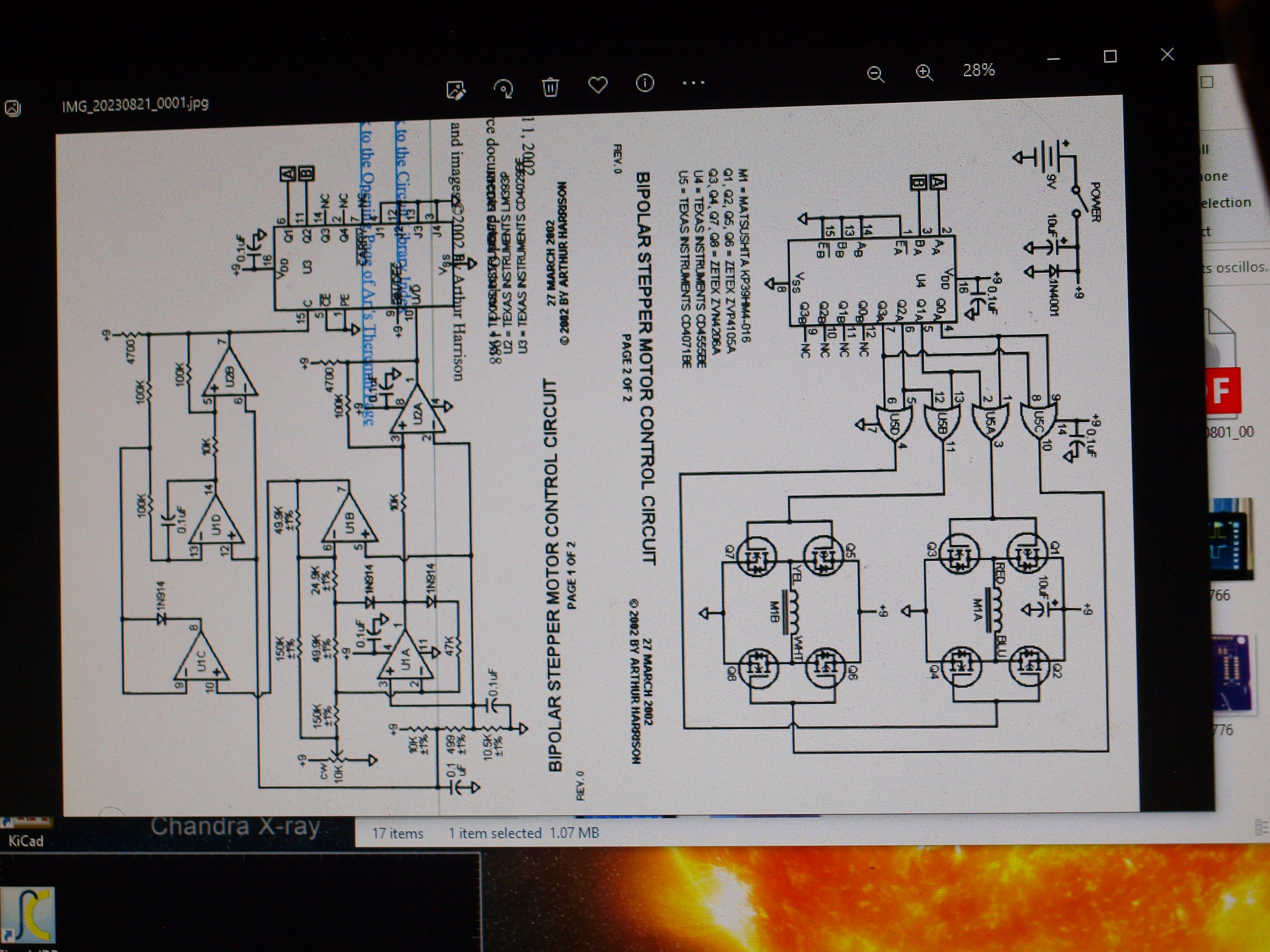
 The last picture is of my rendition of the original circuit.
Comments
How Do You want to step, if you have 2 dc motors connected instead of 1 step motor???
You can either
A use two bridges for 2 dc motors or
B 2 step drive modules which each contain 2 bridges and additional logic for 2 step motors.
For A You need additional position sensor feedback.
For simplicity I would strongly suggest B.
Christof
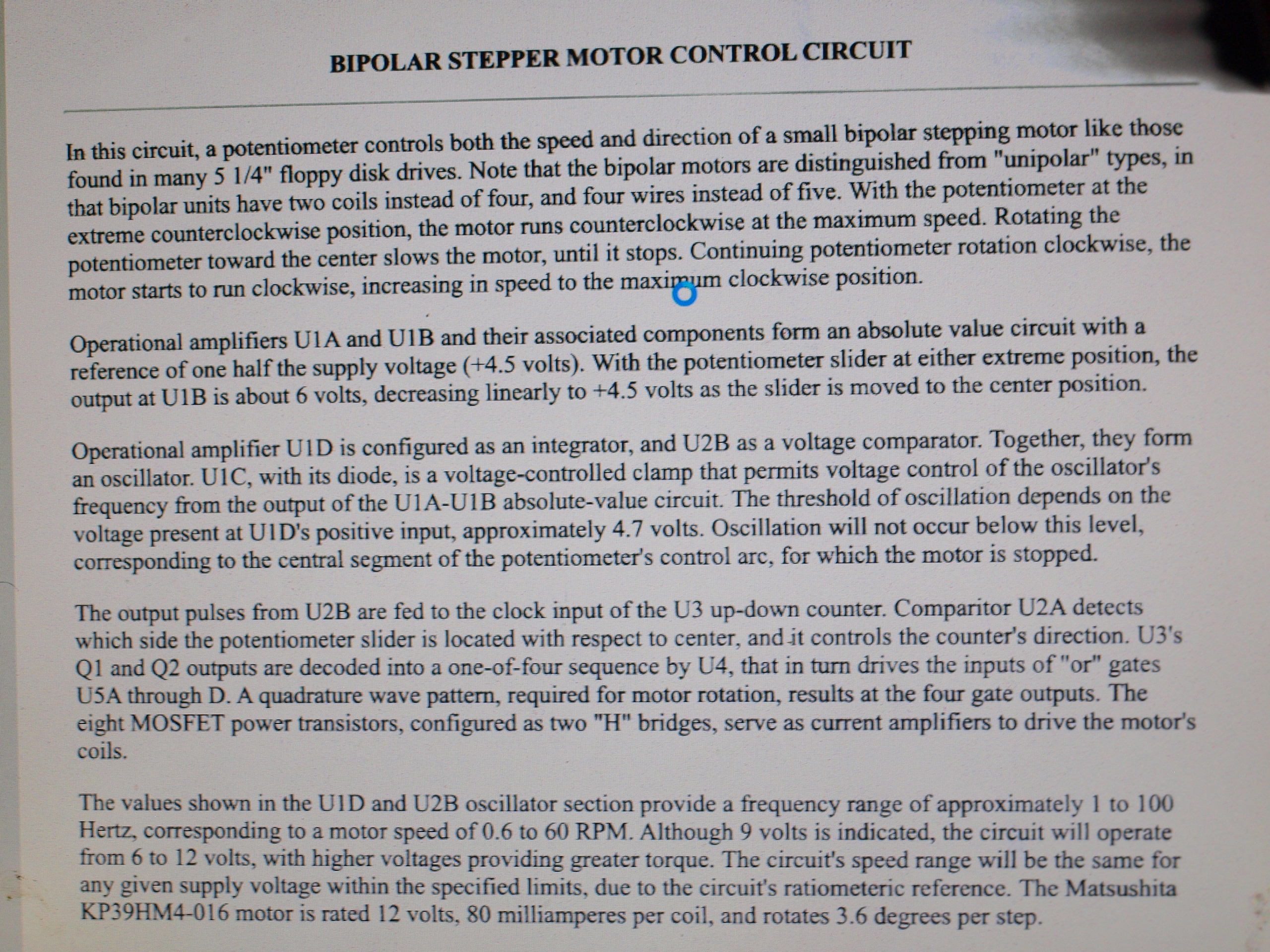
Actually, I already have a dual H Bridge in the Kicad circuit, so each motor is acting as a single coil of a stepper thus two motors = two coils = 1 stepper, I think. I don't want to go thru all the extra work until the circuit proves out. I am wondering if the output voltage of the clock signal is high enough. In the "Art's Theremin Page" circuit the output from U2B might be close to the 9V at the output pin ;your thoughts please. Also, a added note, the steppers draw less than 200ma, # 42 PM 48L BZ . These are Bipolar( only 4 Wires)
If driven from 3v3 logic, you will need level shifters on both clk and dirn.")
Power mosfet gate drivers can manage shifts to 8-15v swings- just ignore their current drive ability
This has probably been mentioned before, but the TC4427 makes a nice level-shifter for going from 3.3v to anything up to 18V. It's actually a MOSFET gate driver, and I've used it in a lighting fixture, but I find it far more useful going from the 3.3v signal from a Propeller to a stiff, 5V signal for servos or other devices.
As a means for testing could I use a pair of 2N3904 to raise the voltage.
Yes, just keep the base & collector resistors on the low side (1k~2k region) for the CLK pin especially.
That has rise and fall time limits that should be in the data sheet.
Hi,
In my opinion, the drive of a step motor is rather different from dc motor drive.
I would strongly recommend to switch over to a module with a special chip. I used a Polulu 1206A stepper motor with a A4988 stepper motor driver module. These modules are cheap, have current control, have microstepping for smooth running, interface with 3v3, are tested and work. Their use is well described. https://www.pololu.com/product/1182
Of course they will not make any sense with dc motors.
Edit: There is no current control in your schematic?!?
The MC3479 looks to be 350mA 7~16.5V full and half step, in DIP16 - so very simple.
Modern stepper parts like DRV8428 have expanded in all directions, (I,V,Steps) but it seems most micro-step parts still have the ability to select full and half step.
Aliexpress seems to have many modules targeting 3-D printers (eg with ATD5833) that are low cost that could save building a large board ?
I really don't understand fully the stepper drivers but the older and simpler driver circuits feed the motors only the amount of current that is needed to do the job. the transistors have to be able to handle the amount of current needed by the motor. most modern steppers are high current and high voltage(30V) like your 3D printers. the motors on my mount are 6-9V @ 200ma or less. I have used Pololu #DRV8834, and the MP6500 units but no function. also I have tried the EasyDriver V4 and no function either. The first DRV8834 drivers did work but I unplugged the motors while still energized which was a fatal mistake, and the next 5 units I bought were non functional and they would not replace them. The original Astro View from Orion used MOSFETS in its circuit but I cannot get the schematics, something about proprietory property.
The simplest designs use the motor resistance and supply voltage to set the current.
It's not easy to find 'dumb' stepper drivers anymore, as the smarter ones are cheap enough to displace them.
The high voltage means the motor gets to step current faster ( V = -L.dI/dT) but they can regulate the current to a lower value than Vpeak/Rmotor.
You would expect the units to at least drive something ?
The Pololu link does suggest these need a sizable electrolytic to avoid spike effects.
The 200mA is low current, but you may want to spec better fets, as a 10 ohm fet drops 2V at 200mA.
You can find better is also cheaper as high volumes are used. eg lcsc shows cheapest are many '2301' P-FETS (20V 2.5A 130mΩ@4.5V,2.5A ) A lower threshold is better for 6-9v operation.
You can get multiple FETs in one package, (eg CJ3439KDW) if you want a simpler PCB layout. Even down to a full set of 4 in a SOT23-8L (AP4580)
I would add a serious clamp zener and large cap across the motor rail.
If you are doing full step, 4 phases, you can also use 4013 and 1/2 4070 as alternate logic (the HEF4013 has a schmitt trigger clock)
example :
https://www.petervis.com/dictionary-of-digital-terms/stepper-motor-using-bjt-transistor/stepper-motor-logic-controller.html
Hi,
Perhaps to buy a step motor and to follow a tutorial like
https://www.makerguides.com/a4988-stepper-motor-driver-arduino-tutorial/
Might be a good starting point.
I have already used the CD4013 and also the CD4027 with the CD4030 which is similar to the CD4070 and they didn't work well if at all . The circuit from "Art's Theremin Page" seems it runs erradically. I am going to experiment with full circuit and see if it works.
Also this is a device that cannot be modified without expending a great deal of money ,and that is something that is in very short supply.
Some parts like HEF4013 have schmitt clocks, (and also this one https://www.lcsc.com/product-detail/Flip-Flops_Slkor-SLKORMICRO-Elec-CD4013_C3041278.html)
which are more tolerant, but 4000 series CMOS should not be too fussy ? Well decoupled and with short leads and < 4k7 pullups, and it should just work with clean signals ?
I am going back to the original circuit " Art's Theremin Page - Bipolar stepper driver " and build the circuit and check the validity of the circuit with my R.A. stepper motor. Then I will try removing different parts and injecting the clock pulse from the microprocessor. Hope I find the answer soon.
Hi,
https://www.theremin.us/Circuit_Library/bioplar_stepper_motor.htm
This is the circuit?
This circuit has no current control.
It is driven with 9V.
This means that it only works OK with a motor that is designed to work with this kind of supply. Most motors have low coil resistance and need an external limitation of current. What is the coil resistance of your R.A. motor? What will be the current? What is the coil resistance of the target motors?
The R.A. motor is a 42PM48L BZ which in some books reads as a unipolar stepper. It only has 4 wires terminating with a modular phone jack. Measured current is less than .20 amps. I am sending a photo of stepper with a picture of a phone charger for size comparison. Also to clarify things I am using a Propeller for the microprocessor.
bbrien,
Your Stepper motor may be one of these.
http://www.motionking.com/Products/PM_Stepper_Motors/42PM_Stepper_Motor.htm
For simple testing, you can also use SPDT microswitch type switches with hardware debounce.
Can be as simple as 1/4 of your 4071 connected OP-IP, & the light drive of the CMOS is easily (very briefly) overdriven by the switch
https://www.eejournal.com/article/ultimate-guide-to-switch-debounce-part-5/
bbrien,
Some stepper motors such as the very old one that Parallax used to sell could be wired as either bipolar or unipolar.
Current flows through a coil in BOTH directions for a BI-polar, while it flows in only ONE direction for a UNI-polar.
If you take a bipolar and stick a wire in the middle of each coil then it becomes a unipolar.
You can also take a unipolar and the remove the commons, then connect 2 of the coils together to make it a bipolar.
Moving a unipolar is easy because you just have to pass current through each coil in sequence.
Usually power is applied to the Common and then each coil has a switch connecting it Ground.
One or two coils is energized at a time IN THE CORRECT ORDER to move the stepper.
An H-Bridge on each coil is the easiest way to move a bipolar stepper since the current must flow back and forth.
You can do this with 4 switches but current must ALWAYS only flow THROUGH the motor.
Hi,
perhaps one some other comments:
For both Propeller P1 and P2 I have also used these boards:
Driver Bridge: L9110 Board with two of these chips
https://www.pollin.de/p/daypower-motorantriebsmodul-motor-9110-810572
They can be controlled with 3V3 logic from the Propeller, but they have no current control and they cannot do microstepping. Full step and half step is easy, you only have to provide the pattern of the two output pins of the processor. You can also switch off the current, which is important, if you want to use battery supply. You need 4 pins for each step motor, but this should be no problem with P2.
I was aware, that you want to use P2 and not Arduino. Frankly speaking, I thought, that it would be much more easy for you to follow a good clear tutorial and perhaps buy a prebuilt dual motor shield. If you use an Ardiuno with 32bit ARM it is likely, that you will have more than enough computing power for your application or you can switch over to P2 after a learning phase. I have used different types of microcontrollers and I always make a table to decide, which controller will be a good choice FOR ME to achieve my project goal. Documentation, libraries, cost, probability of success and fun are important criteria to decide this. Edit: I have now seen, that there is even: https://projecthub.arduino.cc/dEskoG/rduinoscope-a7b248
I have now seen, that Parallax offers a step motor module too: https://www.parallax.com/product/stepper-2-click/ As this has only fixed maximum current limitation of 1.6A, you will not be able to use microstepping with it. But as far as I can see, it will be possible to be used with P2 and for bipolar step motors with sufficient coil resistance (?) what I believe that you have got.
For some effective help in this forum it would be necessary to provide the full code together with the full schematic as applied and with information about the step motors. It is not clear with the information provided, what went wrong "I have tried many different drivers for my mount but none seem to work ". Just remember, that the forum members do not have any information other than what you write or show in pictures.
What computer language do you want to use in your project?
Christof
Anyone have experience with the MIC2981?
Post #15
Craig
Not particularly great by looking at the datasheet - https://ww1.microchip.com/downloads/aemDocuments/documents/APID/ProductDocuments/DataSheets/MIC2981-82-High-Voltage-High-Current-Source-Driver-Array-DS20006727.pdf
It indicates total package capacity of 500 mA. The problem is each output is a chain of one saturated followed by a Darlington pair acting as emitter follower. Large volt drop!
PS: Yes, the MIC2981 is good for 3 volt control. MIC2982 is suited to 5 to 15 volt.
TBD62783 looks much more universal - https://toshiba.semicon-storage.com/info/datasheet_en_20160511.pdf?did=30523
Uses a P-channel so no output diode drops to cause heating. Control signals are very flexible up to 30 Volts.
EDIT: That said, channel on-resistance isn't great at 1.6 ohms. So, 1000 mA would be about the package limit here.
@evanh
Yeah, the volt-drop. In my case, I need to drive some existing 24v relay coils which tend to be quite tolerant.
I have a bunch of these things, hope to test over the weekend.
Craig
Edit: Another thought I had; as I happen to already have a beefy +12v available, I could use this and PWM the control if I need, say, 5v out, right?
Yep, resistive loads can generally be handled that way. Solenoids are relatively resistive.
RF losses become increasingly problematic with higher power and longer paths though. Output filtering and shielded cables is the fix when that becomes an issue.
To Christof: I am presently using a Prop1 with spin. The schematic in the post is taken from the Google images. the bottom FETs are removed since they only disable the H bridges and I ground the N channel FETs. Also I am usingLP0701 and TN0702 FETs in the H bridges. I hope this is enough info to get started. I shall setup and test later today.
As you can see I gave up on the Arts circuit and went to a different circuit I found online at
"https://www. Electro-Tech-online .com" .
For Genetix: I have checked the Motionking site and found a similar stepper in size and shape without the gearbox but it was actually a unipolar motor, these bipolar motors were probably manufactured for a specific company. The kit unfortunately is no longer available at Orion Telescopes.
An actual link to the new circuit would've been nice.
I think it is this one
https://www.electro-tech-online.com/threads/bipolar-stepper-driver-with-4000-line-chips-and-mosfets.149373/
uses XOR and JK FF, 4000 series
Looks good, and has Bridge enable FETs which could be useful for power save in a heavily geared system, if the motor stays put when the current is removed.