

Xbee with Basic Stamp garbage data
 Luis_P
Posts: 246
Luis_P
Posts: 246
in BASIC Stamp
Do anybody has an approach to get rid of garbage data been received by Bs2?
My Bs2 is connected to XBee Pro (end device) Sending a binary character. The receiver is a Zigbee connected on PC. All set in Transparent mode. How do I get rid of all this garbage been received? See picture. Thanks
Comments
I solved this issue. The adapter board I was using is bad. I changed for another vendor and is working. Do not use this adapter board:
https://www.parallax.com/product/xbee-5v-3-3v-adapter-board/
That seems a little harsh ? Surely the adapter is not "bad" ?
Could it be that your circuit was missing pull-up resistors on the RX/TX signals, and perhaps the other vendor board has those on-board already?
I checked the schematic at the link your posted, and there are no pull-ups, so you should expect "garbage" data whilst the pins are floating (before transmissions), unless either you add appropriate resistors to your circuit, or deal with the situation in code, so that you ignore data that arrives before a real transmission - typically done by waiting on a known data-start header value.
Anyway you might have moved on, but mentioning in-case you could actually re-purpose the other adapter boards and save some money or waste in your project.
Hi Von. Maybe you right. I connected the BS2 pin directly to the DIN in the Xbee. Also Im not using the Dout pin on the Xbee. Can you post a drawing how to hook up with resistors?, it may help others with same problem.
Im using an adapter board that also has usb connection, probably the resistors are already in that board.
Thanks
VonSzarvas,
I downloaded just the product manual to look at it, and it's 'borked'.
The headers, footers, and assembly instructions are unreadable.
https://www.parallax.com/package/xbee-5v-3-3v-adapter-board-downloads/
32401-XBee-5V-3.3V-Adapter-v1.2.pdf
On the PDF document I don’t see any instructions to hook up a resistor on the TX/RX lines of the Xbee adapter board.
Looks ok for me. I've downloaded and attached here to compare the file that looks fine here. Maybe you got a bad download, or the pdf reader you are using doesn't support the character set, or something bizarre like that?
Try adding a 10K resistor from DIN to 5V. That 10K value would be good for reasonably high baud rates, and would ensure the XBEE does not receive any floating/garbage data whilst the Basic Stamp is resetting/booting up. Placement of the resistor is not critical, but if long wires between the XBEE and Basic Stamp, then try to put the resistor closer to the XBEE module.
Caveat - I'm assuming you are using the Parallax XBEE adapter board which includes the 3.3V / 5V level shifters. Don't use an adapter that doesn't include level shifting, as 5V driven from the Basic Stamp would probably destroy an XBEE over time- as most XBEEs are rated for 3.3V only "as far as I recall".
Im using this adapter board from “Waveshare” ( B07V7GB5XZ ) I don’t know if includes the 3.3V / 5V level shifters but Im assuming it does. I’ll see if I can find the datasheet or contact Vendor. This board does not gives me any garbage data and is cheaper than the other one:
waveshare XBee USB Adapter UART Communication
https://www.waveshare.com/xbee-usb-adapter.htm
I did a search using "waveshare B07V7GB5XZ" and within 30 seconds found the wiki page that includes a link to a schematic.
Links:
rolling back to your original question... after the garbage, did you receive good data ?
I ask because maybe a pullup was a red-herring, and instead the solution would have been to swap your hookup wires. ie. perhaps you inadvertently had your BStamp output connected to the XBee output pin (instead of the XBee input pin). I've not looked closely at the schematics, but often the "perspective" of labelling varies from product to product, or from one persons logic to another. Especially when serial (and more "complicated" multi-hop serial) is involved. Might be worth a check.
also what Jon said... if you are sticking with that simpler adapter then insert a 4.7k resistor in series at the DIN pin. I don't think either of us can promise that will be a long term safe solution without spending time going over the datasheets, but it's a minimal and quick protection that could save you headaches and costs. Or ensure your Basic Stamp never drives that signal high (just toggling low or hi-z).
Yes I did receive the data and connections are correct. Pin 15 (BS2) to DIN (Xbee board). How about adding a level shifter? Like this one:
https://media.digikey.com/pdf/Data Sheets/Sparkfun PDFs/Bi-Directional-Logic-Level_HookupGuide.pdf
IMO, you don't need that circuit because it's bi-directional -- it's good for single-wire, half-duplex serial and for I2C circuits with mixed voltages.
XBee DOUT can connect directly to the BS2 RX pin (so long as the RX pin is never made an output).
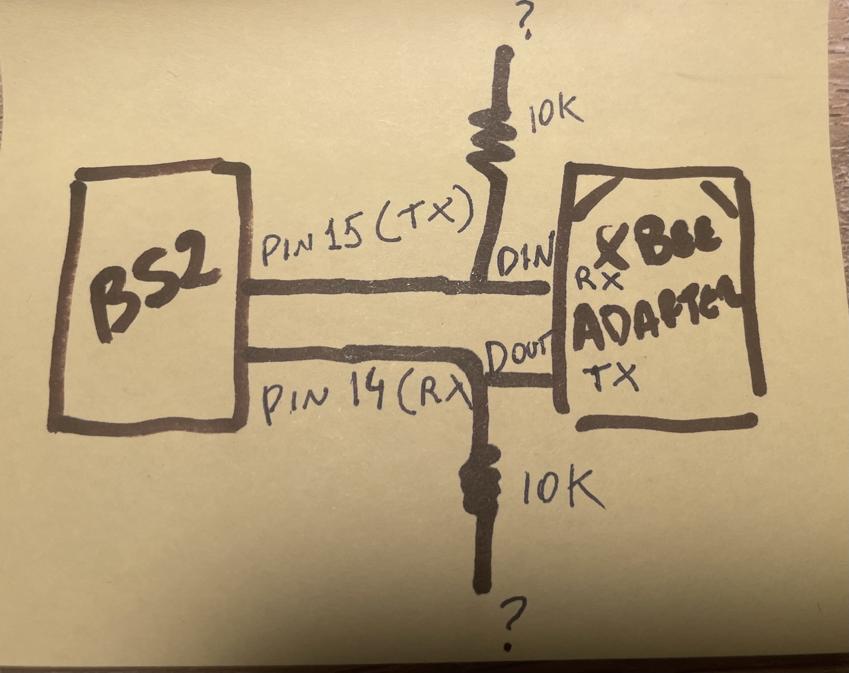
BS2 TX pin can connect to XBee DIN through a 10K resistor.
BS2 TX pin connected to XBee DIN through an NFET level-shifter or simple voltage divider.
Inserting a 10K resistor in the RX line of the BS2 won't hurt anything -- in fact, it will protect the XBee from a programming error.
I will do that. The 10K resistor is a pull down to ground or 5v ? Can I still use the adapter board from Waveshare that doesn’t have a level shifter? Or I have to use the board that has the 3.3V converter? Connection like this? See picture
I would not do that. You still have 5V out of the BS2 going into a 3.3v XBee pin. Put the 10K resistors in series between the devices.
Nevermind. Chris Savage has confirmed (below) that series resistors do not work with XBees. Use a level shifter or voltage divider instead.
It would be nice if you could get away from transparent mode, but you just don't have the memory or processing power in the BS2.
Hey Luis,
Are you running the 5V output of the BS2 directly into the XBee DIN or via the adapter board?
I designed that board. I also drew the schematic. At the time it was designed for the BASIC Stamp Modules because XBee engineering told me that the DIN on the XBee was NOT 5V tolerant, even with a series resistor, because the modules (at least back then) did not have the protection diodes that would normally allow you to use a series resistor. Somewhere there's an AppNote I wrote on 5V / 3.3V interfacing that covers the various ways to connect 5V devices to 3.3V devices. The series resistor is useful when the 3.3V device has protection diodes on the input, in which case the series resistor is just limiting the current that diode has to deal with, which usually isn't very much. So for that particular adapter we needed an IC that could handle the 5V for the BASIC Stamps modules, but talk directly to the XBee at 3.3V.
That adapter was tested using BS2 to BS2, BS2 to Propeller and BS2 to PC (using the USB adapter). I don't have the code anywhere, but Parallax may. There was never any garbage, and no pull-up was used on the BS2 TX pin in those programs. Usually a pull-up would be used on an open-collector output. I hope this helps.
Yes Im connecting BS2 pin 15 to DIN pin on the board, nothing connected directly to the Xbee pins. When I tested the other board from Waveshare I don’t have that issue but will damage the the Bs2 pin at one point because there is not level shift on that board.
Im sure other people may have this issue so we have to clarify. The 10k resistor in the middle of Tx (bs2) and Rx(DIN, Xbee board adapter with shift level) is to protect the Bs2 pin?, to avoid RF grabage data Or this is used only if the Xbee adapter board doesn’t have shift level 5V to 3.3v ?
Also Im going to test this adapter board:
https://www.sparkfun.com/products/11373
@VonSzarvas
@JonnyMac
If you're going to use the SparkFun board, you will probably damage the XBee over time, since the inputs (at least on the modules out in 2010) were not 5V tolerant. The Parallax Adapter has an IC which handles the 5V from the BS2 and connects to the XBee at 3.3V. The SparkFun adapter doesn't do that. A 10K pull-up may help with noise if you have long wires between the BS2 and the XBee adapter, but that won't protect the XBee module and could damage it using the SparkFun adapter.
Do you have a schematic for how you connected the Parallax adapter and the code you used on the BS2? Perhaps I could try to duplicate your results.
EDIT: I did just look at the schematic for that board and it seems to have level shifting for the DIN / DOUT, so you should have an issue using that adapter. There are no tags pointing to the level shifters, so it appears as if the signals go straight through. That said, still trying to figure out why you're having an issue with the Parallax adapter.
This is the schematics. Notice DOUT on the board has no connection but I will have it later. Im only using DIN, 5V input and GND on the adapter board.
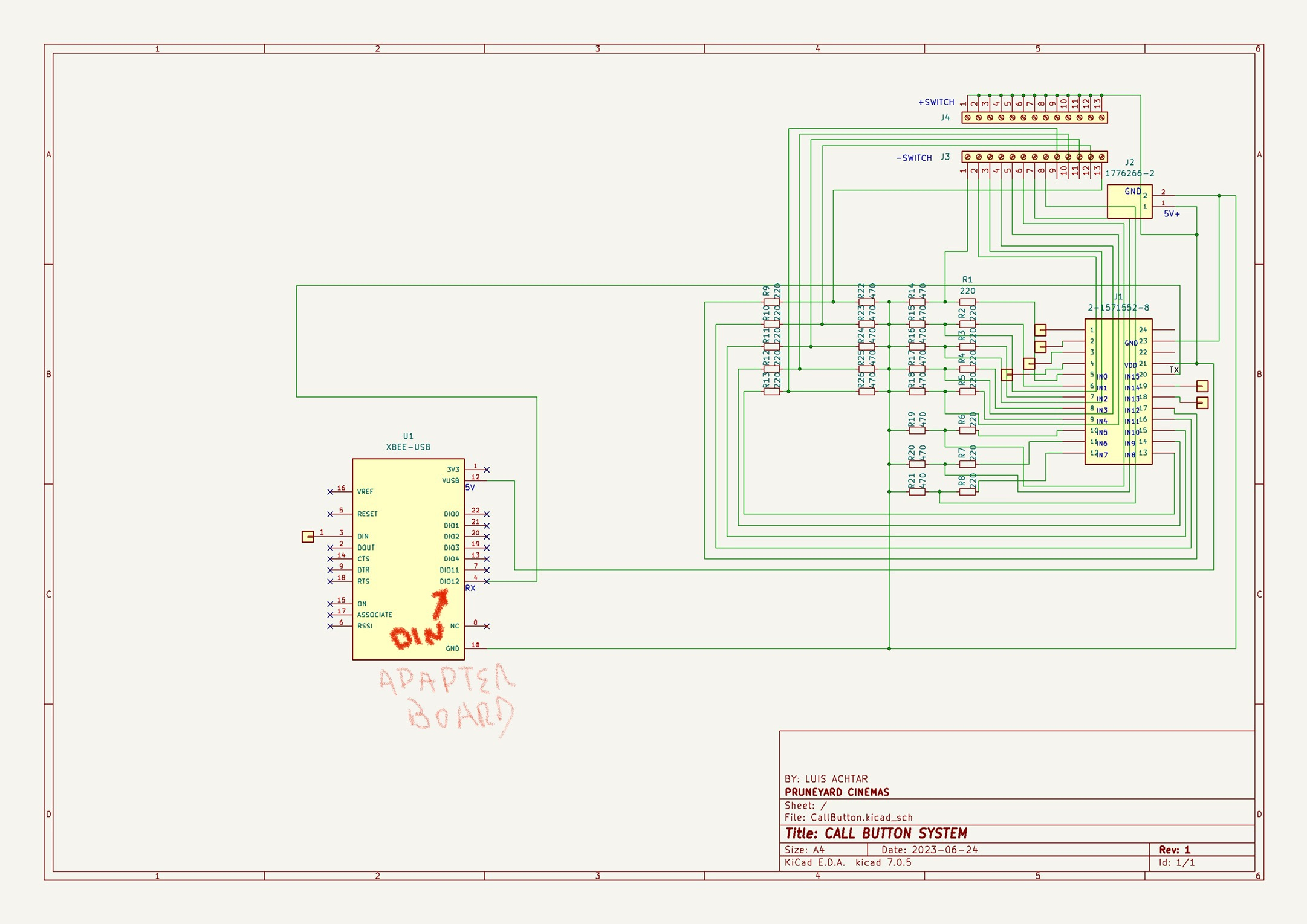
I thought you were using the XBee 5V/3.3V Adapter, which is what you linked at the beginning. But your schematic shows a USB Adapter. Can you confirm?
I used that Symbol just to print my PCB Board because it has the same holes and spacing. Yes Im using your board instead. It make sense?
When I was prototyping I used only wires and does the same thing, senda the data but laso al lot of unwanted characters
On the XBee 5V/3.3V Adapter, your BS2 output would connect to pin 4 of the adapter, and the GND/Vss would connect to pin 1 of the adapter and 5V (Vdd from most BS2 boards) would connect to pin 12 of the adapter (opposite side). With the XBee Module in the adapter, you should be able to run standard serial communication code on the BS2.
What code are you running on the BS2?
Tx is Pin 15. The code works. I except as soon as I power the Bs2 garbage data starts sending right away
SEROUT Tx, Baud, [ $7E, $00, $04, $08, $01, $4E, $44, $64] 'DISCOVERY NODE AT COMMAND
PAUSE 200
SEROUT Tx, Baud, ["PYC1A"]
Okay, one final question...do you have a voltmeter? If so, what do you measure at the power terminals when the power is on?
If that's the case, ignore my suggestions about series resistors and use the MOSFET circuit. Better yet, use a Propeller!")
Let me be clear, I don't know if the CURRENT XBee modules do not have protection diodes on the input pins. 2010 was a long time ago. I'm just going by the information from the time. It's been a long time. The module that the OP is using looks nothing like the ones I have from back then. But, I agree, a Propeller would be a good option.
That is an API message and would likely create issues when running in Transparent mode.
Read this:
-- https://www.digi.com/resources/documentation/Digidocs/90001942-13/concepts/c_xbee_comparing_at_api_modes.htm?TocPath=How XBee devices work|Serial communication|_____2
Beat me to it.") I was originally assuming he was just sending serial packets.
I was originally assuming he was just sending serial packets.
A simple interface between BS2 TX and XBee DIN would be a voltage divider.
6.8K on top gives an output of 2.98v (best choice)
4.7K on top gives an output of 3.4v (XBee max Vin is 3.6v, but could be problem with 3.3v supply on board)
10K on top gives an output of 2.5v (falls below XBee VIH)
So if I switch to the Propeller 1 or 2 I wont have this issue? Do anybody has a working code? Im not familiar with Propeller programing language