

Dead P2 Postmortem Questions
 Duane Degn
Posts: 10,588
Duane Degn
Posts: 10,588
I had my Propeller 2/ESP32 combo board finally working. Then I tried to figure out how much current I could expect a healthy board to pull when it died.
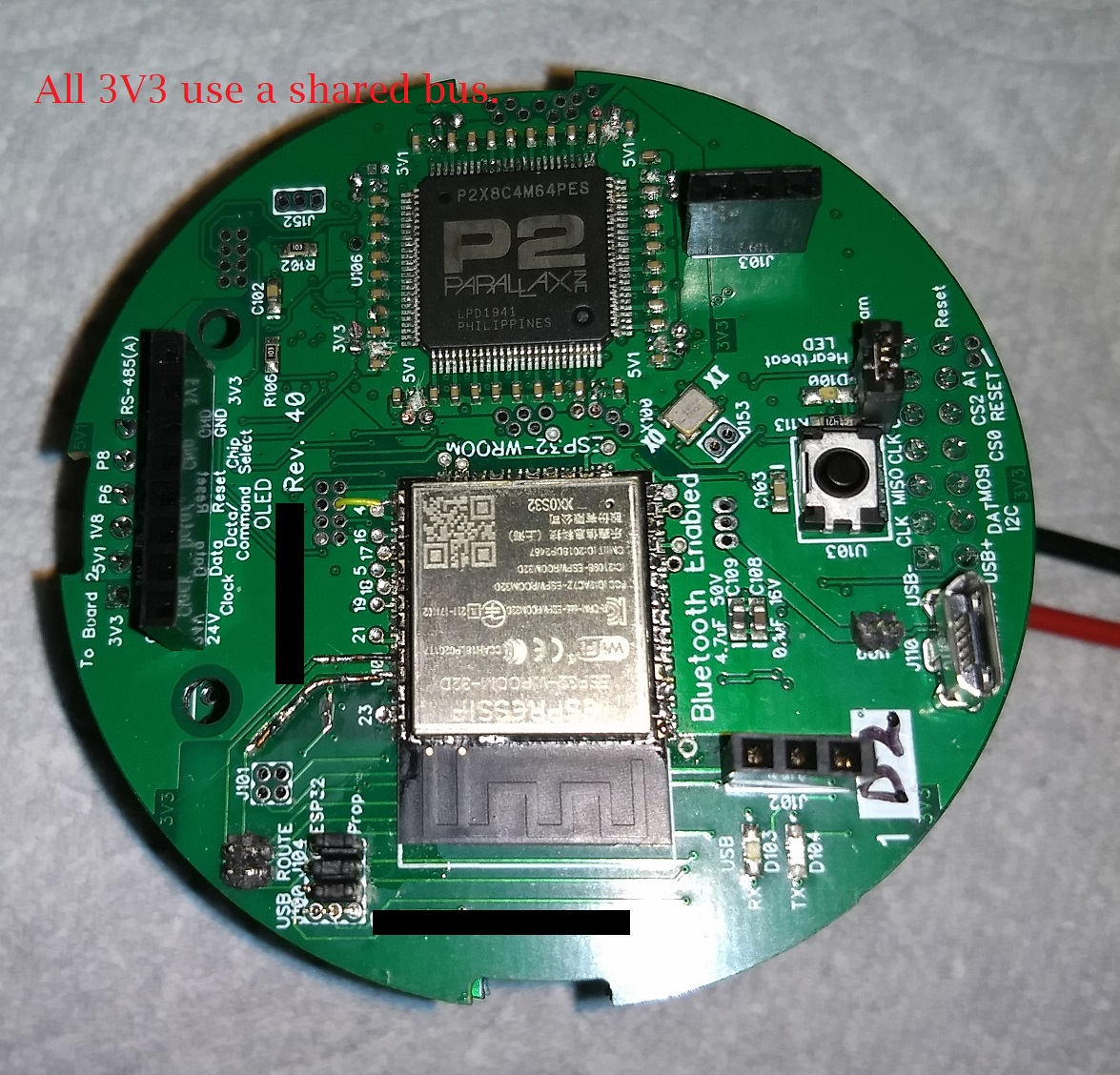
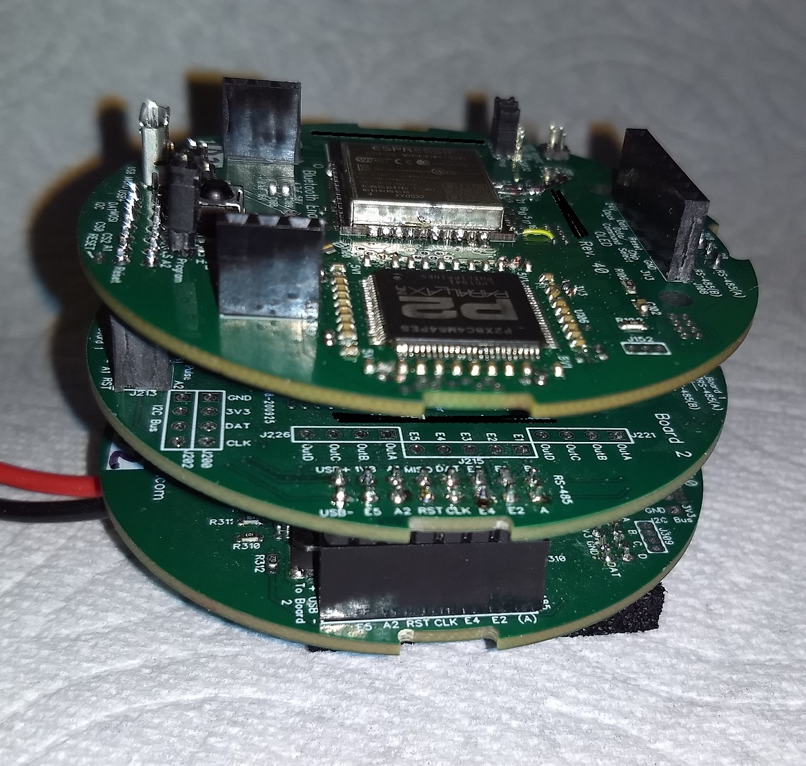
I was powering my stack of boards with a bench supply set to 24VDC. While the Spin2 program was running a "Press any key to start" loop, the stack of boards drew 25mA. At 24V 25mA of current is 0.6 Watts of power. 0.6W seems reasonable will the P2 was executing a light load (its only task was to output to the serial port).
Since the stack drew 25mA at with a light load, I wanted to see if 50mA would be enough current once the main program started. I set the current limit on my supply to 50mA and then started the main part of the Spin2 program. The main program used most of the cogs in order to monitor an IR remote and drive an OLED screen.
Apparently 50mA wasn't enough and the power supply quickly dropped the voltage to limit the current. Obviously the P2 needed more power to run the main code.
A disconnected the board from the power supply and reset the supply to provide the usual 200mA at 24V and tried to run the program again. This time there wasn't any serial output.
I recall blowing the PLL circuit on a couple original Propeller chips so I created a program to simply toggle a LED. The program loaded just fine but there wasn't any activity on the I/O pin I intended to use with the LED. I tried multiple other I/O pins just to be sure, but still no activity.
What did I do to my Propeller 2? What sort of damage allows the P2 to be programmed but doesn't allow the program to run?
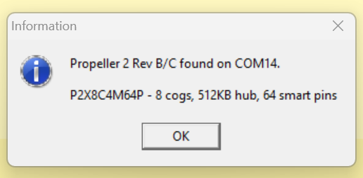
Pressing F7 while using the Propeller Tool generates the usual optimist message when a P2 is found but the P2 doesn't do anything observable other then acknowledging it's there.
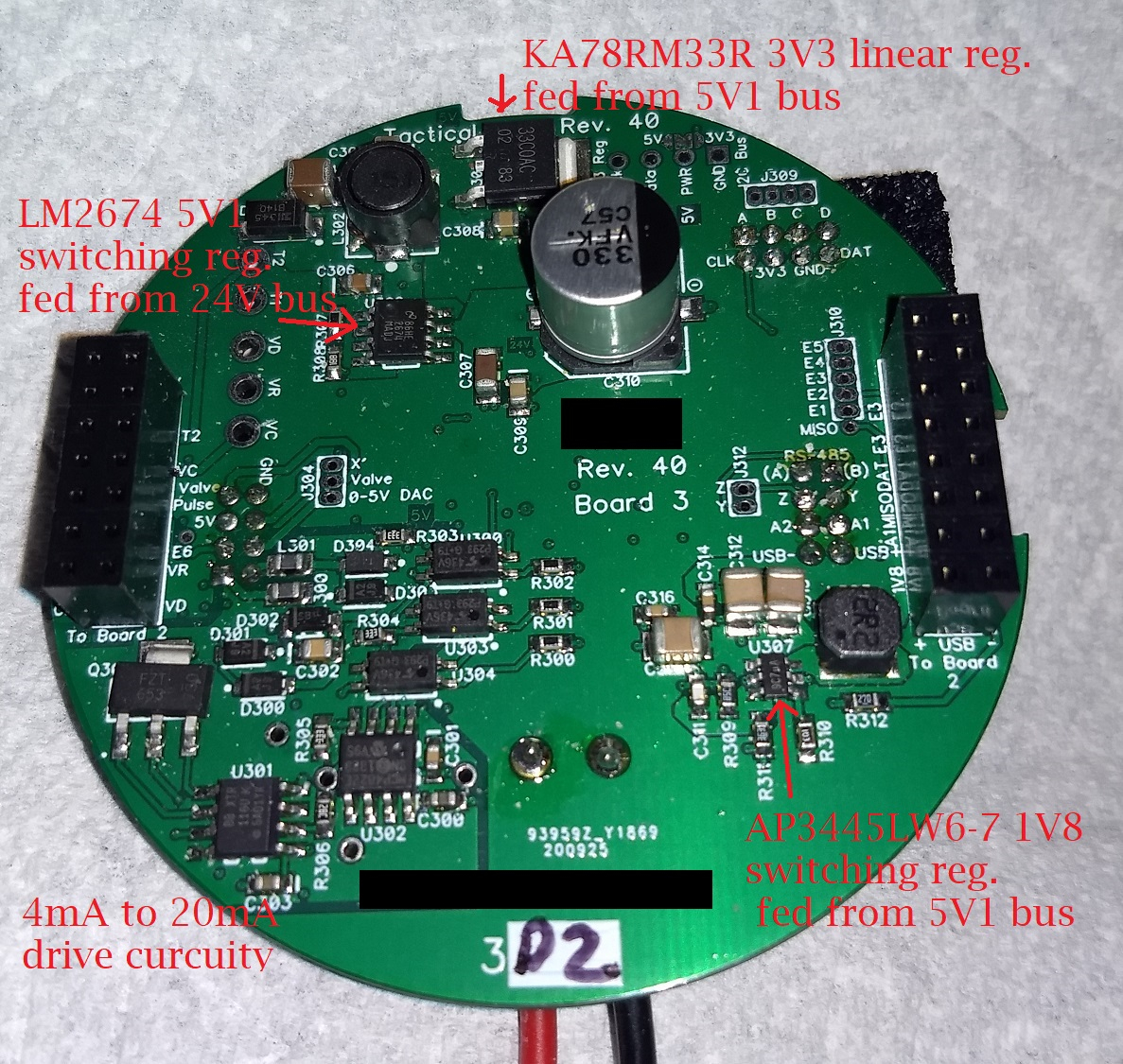
The 3.3V and 1.8V buses still appear to supply power to the chip. I'm using a LM2674 switching regulator to reduce the input voltage from 24V to 5.1V. A linear regulator drops the 5.1V to 3.3V. A AP3445LW6-7 switching regulator is used to drop 5.1V to 1.8V.
Here's a photo of the board which provides the various voltages used by the main P2 board.
I find the process of removing and replacing P2 chips challenging. I would very much like to avoid repeating this experience. The current design is intended to be used as a commercial product (industrial flow meter). I would really like to avoid having the product fail in the field. If I need to redesign the power supply board, I'll do so but I don't know what I did wrong.
(Dang it. I really miss Phil Pilgrim. He always helped me figure out problems like this in the past. I don't think I've asked a question on the forum since Phil passed. Double darn dang it.)
Comments
The PLL or other clock-input-related circuit. The real clock mode is only set when the program starts, the download process uses the RC clock. Try changing your LED program to run in RCFAST mode.
Identification is a really good sign.
No idea why loading a led blinky code wouldn’t work.
The boot process in p2 can be tricky though ..
Maybe see if you can get into the escape diagnostic mode or forth?
If >4 volts was applied to a p2 pin, might kill it. Otherwise very hard to kill.
I remember the P1 pll being often the first thing to die. Don’t think this is the case for P2 though. Believe seen cases where some pins are dead but otherwise OK. Problem might be if high voltage happened in the specific pin group where the pll circuit is though. That might prevent pll from working.
Generally, I’ve seen that if ids to prop tool it’s ok. But, never know for sure I guess if 24 volts is nearby…
Thanks for the suggestion. It still didn't work.
I ran the same code on a P2 Evaluation Board and the LED blinked fine. It just blinked a lot slower than when using the original program.
I would have thought so but I'm pretty sure I killed the chip.
Even if the blinking code worked, I still could not use the board for intended purpose. I just really don't want to kill any more boards. I designed and built the board myself and the fine pitch of the P2 chips is challenging for me to solder even with a proper solder paste screen. It's even harder if I have to just replace the single chip.
Thanks to both of you for the help.
Edit: I should add the design uses a design from Parallax as a starting point.
Hopefully the problem was with the way my power supply limits current. Hopefully normal fixed supplies won't cause the same problem.
Try that escape mechanism in serial terminal or booting into forth
Bet that works
Am I correct to assume the P2 uses IO pin 63 to program it? So if the P2 can be programmed, then IO pin 63 should be a working pin, right? Is IO pin 62 used to acknowledge the program being received correctly? I suppose the most likely pin to still be working (assuming the program is received) should be IO pin 62, right?
I tried this simple code:
PUB Main()

  repeat
    pintoggle(62)
    waitms(500)
(Edit: I also tried "pintoggle(63)" without success.)
The above code will blink a connected LED on the P2 Evaluation Board but the LED does not blink on my board.
I'm confused.
I don't know what you mean by that. Any suggestions on where to find documentation on this process?
I heard a few times that forth is much better than sliced bread but I haven't tried it myself. I don't want to spend time right now using forth for the first time.
Thank you for the suggestions. I'll try to figure out the escape sequence.
The flexprop gui has special commands to enter these modes. I’d try that next…
If p2 identify works that means a lot of things are working.
I’d be optimistic…
Yes - you should be able to use a terminal too
My notes say this
PC Sender: (into P63) “> Prop_Chk 0 0 0 0“+CR (Note the space before “Prop_Chk” - this lets the loader learn the baud rate (now > ))
P2 Loader (from P62) CR+LF+“Prop_Ver Au”+CR+LF Au is A..Z, u or p 15Ch CR/LF (Hex 0D0A)
If you get an ID echo, you must have Core Vdd, and at least P63 bank has 3v3 OK
Enter TAQOZ from reset(esc), ie $3E,$20,$1B, then pause >195ms at 115200
simple test Pin 2 generate a 10% PWM with a resolution of 1,000 counts with minimum clock division.
Echo: TAQOZ#
Send: 2 PIN 100 1000 1 PWM
Echo: ok
First, I prefer to use separate regulators for each pin group, rather than one regulator supplies all. You could just have a few bad pins. I know with the P1 you can blow the counters and the rest of the chip seems normal. Bite the bullet and remove P2 with your hot air rework station. Then power the board and check all of your supply pins. Do you have good contact on your center back plane heat sink pad
It does sound like the crystal oscillator pins have died. With Proptool, RCFAST might only work for pure Pasm2 programs.
EDIT: Here's a pure Pasm2 pin P56 toggle for Eval LED that keeps sysclock with RCFAST selected:
CON _rcfast DAT ORG loop drvnot #56 waitx ##25_000_000 / 4 jmp #looprcfast doesn't work with Spin2 in Prop Tool?
Wonder why that is... Think works for P1.
BTW: I have replaced a P2 chip before using hot air gun. Wasn't pretty or fun and took forever, but is possible.
What regulators do you like to use with the P2?
I purchased some of the same regulators Parallax included in the P2 Evaluation Board BOM. I also included the component footprint on the layout. When it came time to solder the regulators to the board, I realized even with a solder paste stencil, I didn't have enough skill to successfully solder the tiny (microscopic IMO) regulators.
Here's part of the layout showing the footprints to a couple of these regulators.
I added solder jumpers which would allow me to use a single 3.3V regulator. Since I didn't feel like I could solder the small regulator, I opted to use the jumpers. The red lines in the capture above shows where these solder jumpers get shorted.
I'll likely give the small regulators a try once I feel I've improved my smt solder skills enough.
I'll likely do this in the future. I want to wait to learn what I can from this failure first. I have several PCBs of the same design which need to be reworked. The one I've described was just the first board I got the P2, ESP32 and FTDI chips all happy.
Thanks for the test code. The code you provided works fine with my Evaluation Board but the code does not light up an LED attached to P56 on my problem board. I tried the code using P62 as well without luck. With the code loaded and a LED connected to P62, the LED has a steady faintly glow. I'm pretty sure the faint glow of the LED is caused by the 10K pullup resistor to 3.3V.
Thanks for the suggestion.
I'm embarrassed to say, I don't know what you're trying to tell. I know the P2 has all sorts of cool debug features but I haven't taken time to learn these features.
I was working on a project using the original Propeller but I kept running out of RAM. I'm trying to get the project converted over to the P2. I know the P2 has all sorts of amazing features but the main feature I was interested in was the increase in RAM. The extra IO pins are also great.
I really need to take some time and get up to speed on the debug features.
One excuse, I can provide is the program I'm working on uses the main USB connection for user input. I use a Prop Plug connected to a different pair of IO pins for debugging.
Thanks for taking time to suggest ways debug the chip even though I don't know enough right now to take advantage of your suggestions.
I've attempted this myself but I have yet to do it successfully. I just ordered a stencil for the P2 chip only. I have had success soldering a P2 using solder paste and a stencil so hopefully a small stencil will allow me to make the repair.
Thanks for all the help guys. It does my heart good.
I’d have to check what I used. I had to go with what was available at the time. A good set of tweezers helps with the part placement. I was just wondering what type of flow meter are you building, is it a air velocity immersion type etc.
This is good for evaluation boards but in production designs it adds unnecessary complexity and cost. All of my board designs use a single LDO for 3.3V and an SMPS for 1.8V and I never had problems. Wait... that's not true, one of my servo boards uses an additional 3.3 regulator for the ADC imput pin group to decouple those from the rest of the IO pins to improve precision and decrease noise.
But 8 regulators are just overkill. They only cost a few cents but in a real production test you have to measure all the voltages so that's 7 extra test pins.
Normally, the Propeller is really hard to kill. I've assembled 100+ boards and from time to time I had some solder bridges. If something didn't work I just checked for bridges and removed them. No propeller was ever damaged except for one where I accidentally soldered it in 90° rotated.
@ManAtWork I'm with you regarding regulators. I can maybe see wanting local LDOs for better analog ADC, but single SMPS seems fine to me.
@"Duane Degn" I use the "special" command on the FlexProp menu to enter those special debugging modes:
For removing the P2, I cranked up heat on air gun and let it cook until bottom released, think removed with two pairs of tweezers somehow.
Maybe next time, I'll turn the board upside down and see if I can make it drop off. Not sure if that'd work though.
For putting in the new P2, can't remember exactly how I did it. But, probably just used heat gun again. Probably didn't even clean off old solder...
My usual trick for the pins is to put on a bunch of solder so all pins are bridged and then clean up with solder wick.