P2 outputting hi def using AHD video camera format?
 rogloh
Posts: 6,236
I was thinking of installing one of those updated head units for a car with support for Android/CarPlay etc in order to drag an older car I still use out of the pre bluetooth stone age. These devices usually also support reversing camera inputs which I have no real use for, but was considering whether I might just feed a Prop2 generated signal for additional information display to the screen in the car. I believe most of these units can detect a reversing light input powered at 12V or just switch when the camera signal is active and display the video signal from that source to the LCD panel automatically which is handy.
Of course I'm confident that standard NTSC/PAL signals from a P2 could be generated and displayed but the better head units with larger screens can also support higher resolution (720p or 1080p HD) signals over analog with standards such as AHD, which is commonly used for more modern security cameras (CCTV), along with HD-TVI, HD-CVI.
In some digging about online I've not been able to find too much information about this AHD camera video format, but it seems like it might just be a fast CVBS type of signal which the P2 could output. Anyone here ever messed about with this video format or have waveform captures of it? I guess I could just go buy a cheap camera and check it out with a scope at some point.
This youtube video from 23:54 onwards showed an example of the type of signal these cameras output. 
Being an analog signal its horizontal resolution is essentially going to be variable and limited by the overall system bandwidth and so is only really dependent on the choice of pixel clock rate the P2 uses.
As far as number of video lines goes the P2 is fully flexible with what it generates, but I'm not too sure of the colour burst stuff for AHD. I found one page here which seems to suggest it might use 11.55MHz (or 24MHz?) for the colour burst subcarrier instead of the usual 3.57954MHz. Though I'm unsure if I'm reading this table correctly, or how precise it is.
https://shopdelta.eu/video-standards-in-cctv_l2_aid752.html
The P2 should be able to generate a 24MHz colour burst quite precisely without drift when the P2 is clocked at 192MHz (assuming it is truly using 24MHz and not just rounded from something else).
I guess if it didn't work out and the P2 couldn't generate AHD colour information in the right format then it could potentially work in a B&W mono mode (which is still useful for informational display), but having some colour control could be handy even if it is the "wrong" colour, as it would allow a nicer interface to be presented. I could also just fall back to 480 line NTSC with 960H resolution or something.
I may eventually use such a capability to display CAN dumps and/or audio playlists/settings etc. I hope to also tap into the car's M-BUS CD changer protocol and having a P2 could be useful for that (or maybe just an Arduino would be okay for that too...TBD).


Comments
Don't need a particular clock speed. Just need to make sure that the ratios all match up (including some XZERO somewhere) to avoid dot crawl.
Also, the linked page just has whacky linebreaks, it seems to say that the carrier is 11.55 for "720p" and 24 Mhz for "1080p" (is it really progressive?)
Yeah the data presented in that cell was a little confusing. The table also says it has a 25Hz maximum frame rate with a bandwidth of 33MHz for 1080p. So if you figure 1125 lines x 25Hz you get a 28.125kHz line rate. Divide that into 66MHz (2 analogue pixels per Hz max) and you can send ~2346 pixels per line. So progressive 1080p25 should be doable with enough time for blanking.
Might first try to run a P2 at 192MHz and use sysclk/3 for pixels, the numbers should work cleanly from that too if there is enough blanking time, unless there are sampling problems with dot clocks being multiples of colour burst frequencies etc.
I reckon it's worth a try anyway once I get one of these LCD head units to receive the signal which may still take some time. A P2 should be flexible enough to test it out.
If it works we will have to hack NeoYume to play games in cars via reversing camera inputs!
Cops would love that.
Where it says something like 1080p it is saying the two interlaced fields are being used alternately to send half of a still image in each field. Importantly, it uses the same bandwidth as interlace.
What PC weenies commonly call progressive scan is actually sequential scan. Which is entirely amusing given that progressive JPEGs have a similarity in behaviour to progressive scan. Your average VGA mode is sequential scan and is double the bandwidth for the same content.
Somewhere in the past there was a sales pitch done to convince the average joe that progressive is superior to interlace when it most definitely is not. I think the sales pitch was oriented around convincing us that 24 FPS films were somehow better than higher frame rates. And likewise, 25/30 FPS TV programs were somehow better than 50/60 FPS.
Yeah given it is likely outputting very NTSC like video signals it would make sense to probably send 540 active lines on each field of the frame and then deinterlace it into a full frame. Probably it just generates 562.5 total lines per field but it would be good to check the output of an AHD camera on the scope and feed its sync pulses on a logic analyser (to count them and check the serration stuff with half lines etc).
Bether?
P: is better at static frame content, but shutter at moving frame like fast pano, rolling bals. Every frame has full content. And twice the size of I at same frame rate
I: feel steady at moving picture content, the refresh is shuttering 1/2 line. Eyes integrate them and smooth the movement out. And half the size of P
For broadcast the better choice is P these day's. P give an easy way to encode to different contents TV, Web ... P=>I is easy, the other way round not.
That should already work with the regular SDTV output
But that's not what "1080p" means. Since this is a post-CRT format, I would fully expect it to just send full frames in order at 25 fps or whatever.
DVD was very much defined in the times of CRTs. And even if it wasn't, progressive scan was still a transmission and storage method that was built on analogue TV signalling. It was never a PC thing, just PC weenies completely misunderstood and decided it was the same as VGA's sequential scan.
I'm too lazy to break down this utter nonsense one-by-one now, but what you're thinking about (single coherent frames split over two interlace-style fields) is called "segmented frame" and really only exists either as a consequence of converting 30/25 fps progressive material to 50/60 fps interlace for display or processing. What everyone calls progressive scan is full 60/50 frames per second sequentially. Thus the confusion over AHD's alleged "1080p 25 FPS", which either implies that the "p" is wrongfully applied and it is really a 50Hz interlaced format or that it is a 25Hz slow-scan progressive format (which seems more likely to me).
All this has nothing to do with DVDs or JPEGs. The former always store low-framerate MPEG-2 with a flag telling the player whether the video is supposedly interlaced (in which case the two fields are extracted from one frame). The "progressive" mode in the latter really means "progressive loading" and has nothing to do with live video formats.
There's no transmission conversion since it just sits on the interlaced signal. If a TV decides to do it's own conversion internally for upscaling/interpolating/de-interlacing then that's its prerogative.
I referenced JPEG because it was bourne of the same era and demonstrates the same progressiveness in how the image is multi-pass constructed. Progressive scan video is just two passes rather than several.
The term "progressive scan" never existed before that.
Progressive is one scan by definition. Please stop giving me headaches.
You have bought up a good point. This is not a storage format, it's the transmission signalling/timings. It was only a storage format for analogue video tapes and laser discs.
except (in)famous 1024x768 interlaced mode on VGA monitors that abuses them to display higher resolutions than they were capable of. Then a conductive black mesh needed to be hanged on the screen to reduce the electromagnetic field that comes from that monitor... and make the picture quality even worse. And then these new, shiny, 15", LR, NI monitors (Low Radiation, Non-Interlace) that don't need these meshes.
I think these meshes was as efficient as these patented (=very expensive) bed sheets with red dot pattern on them to enhance sleep...
These interlaced modes are invented for TVs to get high frame rate and "high" (at these times) picture resolution at the same time. Good for analog television, a nightmare for digital storage formats.
Interlace has worked quite well with modern TVs too. They can de-interlace much more consistently than they can interpolate (frame adding). Interpolation often stutters and completely falls over with footage that has gone through cheap framerate conversion before transmission. Drone and smartphone footage is bad for this.
I looked at the signal from 5MP and 4K TVI cameras. Even modified my NTSC capture program for the 5MP version. Of course, it was black and white because the P2 ADC sampling rate was much lower than the colorburst. Had to discard 3 of 4 horizontal lines to get the image to fit into hub memory.
The 5MP signal has 25khz line rate, 12.5Hz frame rate. Non-interlaced.
The 4K signal has 33.75khz line rate, 15Hz frame rate. Non-interlaced.
I think it's not simply sped up NTSC/PAL. I've never seen dot crawl on a TVI or AHD signal. I'm not worried about that. I've seen at least 1 paper from the BBC on a PAL compatible system that eliminates dot craw with certain processing on both the transmit and receive ends. There is one line in the frame with a constant sine wave for the whole image width. It might be a clock signal or to measure cable attenuation. I think the P2 could be coaxed into generating these signals.
I didn't think there was much use in trying to generate these high resolution signals from the P2. It just doesn't have enough memory. Maybe it would make a nice text mode. At 1080p or below, component will work without needing an expensive converter box. Roger, you may have found an application for the P2 to generate an AHD signal.
Cool, thanks for taking a look at your cameras' outputs SaucySoliton.
Yes based on that data, it appears to be well within the capabilities of a P2 to output a signal that should display something. The colour is where things might differ but will need experiments to see what can be done there. I won't worry about the memory requirements, and for 1080p I can use PSRAM or HyperRAM as a frame buffer with my video driver if high colour bit depths are needed. Text is fine from HUB. With the slow scan rates vs real HD, it should be able to do even deeper colour too from an external memory without exceeding memory bandwidth sooner.
I mainly like the dead simple single wire CVBS like interface into a car head unit's LCD panel if it can do high resolution with good clarity. Should let me display whatever I want from the P2 to the screen easily.
Funnily enough I actually have my car radio apart right now and out of the car taking a look at wiring connections and space etc. Don't have the panel or head unit yet but just exploring what might be possible to fit etc and whether there might be showstoppers for this idea.
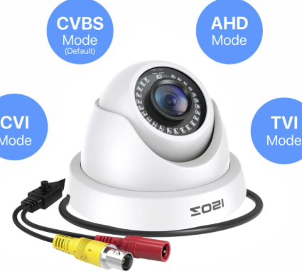
Just ordered one of these 4-in-1 1080p security cameras that is switchable between CVBS, AHD, CVI and TVI modes. It's potentially pretty crappy quality as this thing only cost me ~AUD$24 shipped but should do well enough for an experiment. Will try to hook it up to a scope once it arrives to see what particular sync and timing format it generates in these modes, and hopefully I can modify my P2 video driver to try to synthesize something similar on an output pin.
I don't think I'll be able to measure the real colour burst frequency though, it would need far better equipment than I have to extract/measure it. With any luck that table comparison information originally linked above will be good enough to use for obtaining some colour output if it's accurate.
Will also need to obtain a suitable LCD head unit screen at some point to see if the P2 analog output actually displays something, though I'm waiting for something else first before I intend to order that.
One of these could be good too and let us see the P2 outputting AHD etc on an HDMI monitor for signal validation (although it does add another variable in the full signal path).
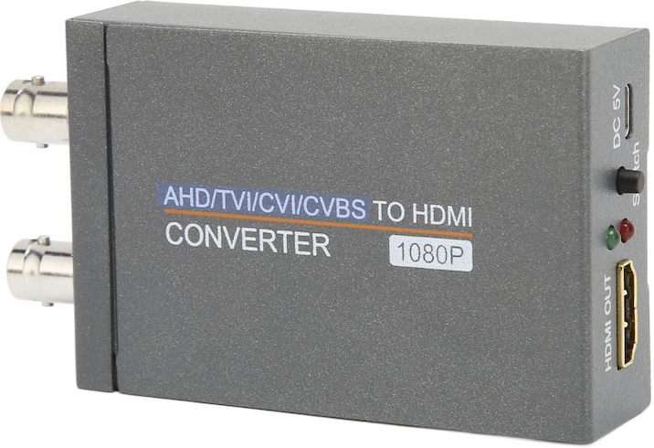
Update: just ordered one for testing, may also come in handy later for feeding this type of camera input to a TV or capture device.
The camera I ordered arrived today and I tried it out with CVBS and it works . Hooked it up to my old Rigol scope and it shows the normal video line counts in this composite mode. This scope does have a video triggering mode but I was not sure if it could handle non-standard frames with lots of video lines, as it was intended for typical PAL/NTSC systems. When I switched the camera output to AHD mode, with the right trigger level it could trigger and I can see a video line but sure enough I could not do the normal odd/even/line#/all lines video triggering modes as the count and line rate is totally different now. Maybe this effort will finally convince me to go buy a decent scope.
What I found so far...
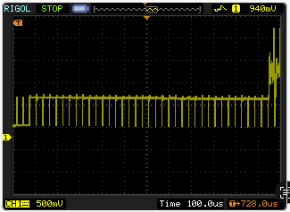
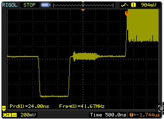
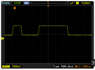
In AHD HD-TVI mode this 1080p camera seems to send 25Hz frames, the line frequency is something around 28kHz and it sends a fixed frequency on the second last line before the sync pulses invert. There are 45 non video lines, so the count is very likely 1125 total which is the standard value for 1080 active lines. The fixed frequency on the second last line appears to be around 29MHz, but I'm not confident due to the limited BW of this scope (50MHz) and it might be double that (which is around the BW of the AHDHD-TVI signal itself). The colour burst amplitude was low on the scope but appears to be close to 41.MHz (was fluctuating a bit due to a poor trigger). The information I found here says it should be 42MHz for 1080p which is pretty consistent anyway:
https://shopdelta.eu/video-standards-in-cctv_l2_aid752.html
Start of vertical sync portion:
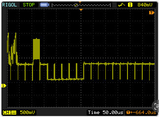
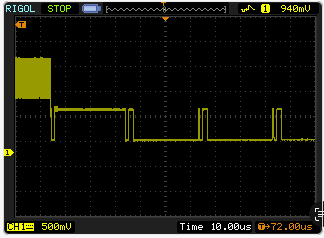
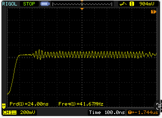
End of second last line with fixed frequency:
End of frame sync portion:
Sync pulse for a normal line:
Color burst:
The inverted (vertical sync) pulses seem to be different too:
I was wondering if the P2 can be used to detect AHD/TVI/CVI video line syncs using its smart pin pad comparator mode with a threshold voltage set to a level just a bit blacker than black and then issuing an external trigger signal from a P2 pin to a scope depending on which video line you want to observe.
I've not used the P2 comparator mode before but this seems like probably something it should be able to do and could be useful here to trigger a scope externally and look at specific line(s) in detail.
Just took a look at this CCTV camera's HD-CVI output mode as well, and noticed a few differences compared to AHDHD-TVI. It uses half lines in the sync portion and different sync tip widths. This also seemed to output 1080p using a 30Hz frame rate not 25Hz. Still 1125 effective lines.
End of frame, start of vertical sync:
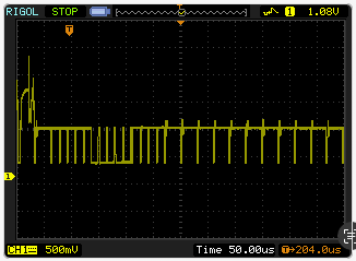
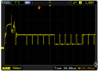
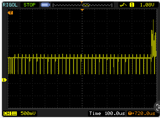
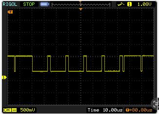
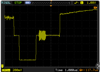
More detail showing half lines:
45 non-video lines total:
Vertical Sync portion:
Wider sync pulses (~2us) on normal lines vs AHD:
I also had a quick look at HD-TVI mode but haven't noticed much difference on first glance vs AHD. Must be something different in there though, will keep digging there...might be colourburst frequency related.
There was something weird about the manual switch settings in this camera, they behave inconsistently vs the menu in the CVBS mode. After using that menu to switch output modes I now believe the first posted pictures above was actually the TVI mode (not AHD as I first thought). The real AHD output is shown below. It uses half lines for sync and puts some sort of test pattern on 4 scan lines in the blanking portion. When I checked the table and the colourburst frequencies for each mode they seemed to line up much better now too with what my scope reports (not that it's 100% accurate).
Sync portion:
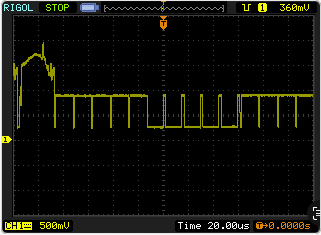
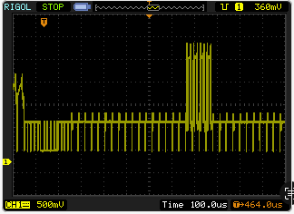
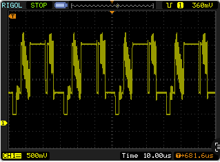
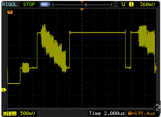
Use of blanking lines:
4 test pattern lines:
More detail:
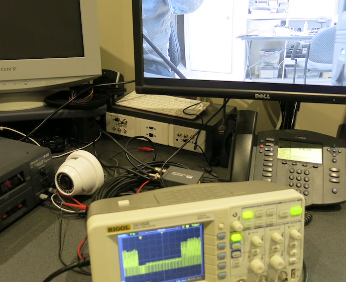
Just received that AHD/TVI/CVI to HDMI converter this afternoon (pretty fast from aliexpress!) and tried it out getting the camera output into my DVI monitor. Seems to be working with all analog HD modes that this camera supports at both 1080p25 and 1080p30 (it retimes both to 60Hz). So now I have everything I need to begin to code up some tests and use a P2 to synthesize something similar and then see what I get on this Dell monitor. I can also observe the same analog signal on the scope as well because it also re-outputs on a BNC which is nice. Even had a couple of 75 ohm BNC terminated coax cables still laying around I could use right away.
Could P2 output 4k video with just one pin over AHD/TVI/CVI?
These standards do mention 4k UHD and in theory if it can be done by the P2 at all using AHD/TVI/CVI it should need only one pin, yes. Of course this is assuming it can generate the pixel data rate and encode the signal in the correct way with the P2 HW. You'd need to ensure that the frame rate and line rate and colour depth don't exceed the streamer bandwidth. The information found did talk about 12.5Hz video frame rate for higher resolutions and 12.5 x 2250 lines = 28.12514kHz line rate. If you sent the pixels at around 148.5MHz you could probably do 4k worth of active pixels on each line. So maybe a 300MHz P2 could do 8bpp 4k at this lower refresh rate out of some external memory.
Over this weekend I modified my p2 video driver's non-interlaced PAL to generate 1125 lines instead of 625 and sent something resembling HD-CVI at 25Hz, but so far the HD-CVI to HDMI converter I have did not appear to detect any valid signal and just presented its colour bars which it does without any input signal. I got the line timing visibly pretty close on the scope (used the camera as a reference on one channel and the P2 signal to compare it with on the other channel) I'm not sure if I've got the colour frequency wrong, or it's just very picky with certain things. Will keep trying. I should remove the alternating line thing too which may be affecting things if it is not required.
I found this information too which has some more information, but was focussed on 720p instead. It talked about a 37.125MHz colour clock as well as a 58.559489MHz clock which were not mentioned in the information I used from that brief table for 1080p. I firstly used 38MHz so there's probably a good chance it was incorrect. I also tried 37.125MHz later as well but that didn't help either. Maybe it actually needs to be 58.559MHz and when I measured it it only showed up as around half of this due to poor BW on the scope. I guess I can try to double it.
https://www.edn.com/transmitting-hd-video-over-rg-59-cable/
I could also try the 30Hz variant and the other two standards though they need more work to synthesize the special lines I noticed above.
Yes, I just got something to display on the screen and it reports AHD 1080p!
Looks like the colour is still messed up but it's displaying something now. I just had the total line count wrong due to the half line counts. It's now sending 1125 lines total. I think I can make some progress.
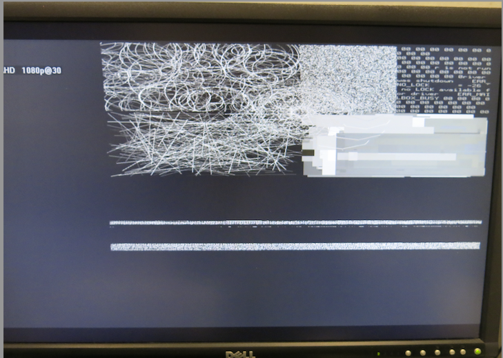
Every now and again I see some colour... It's trying hard but I just don't think I have the correct frequencies as I don't know what they are meant to be. This was 37.8MHz I think (still tweaking). Video animation freezes too so I think it's locking up for some reason. I don't flip the colour burst V each alternating line either, so it behaves something more like NTSC but with the PAL CQ/CI settings. It doesn't seem to like the flip.
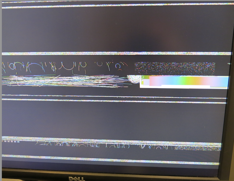
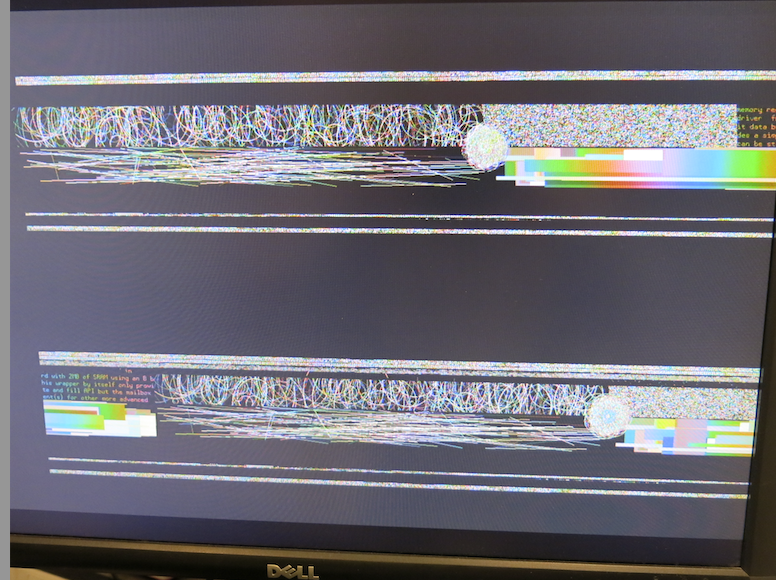
Had an attempt at generating some AHD signals instead of HD-CVI today and was finally able to get some colour bars showing up (though I had to use the NTSC colour burst not PAL). Apologies for the poor quality photo, was hard to get colours showing up right with my lighting and that Moiré pattern was not visible in person.
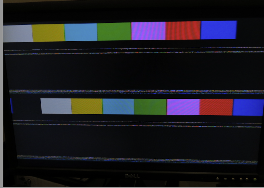
To get to this point I had to reverse engineer things somewhat by homing in on the carrier frequency visibly with dynamic adjustment of my driver's current CFRQ value by pressing console keys to increment/decrement its value and and observing the beat frequency "direction" and number of different rainbows showing up per colour bar. The subcarrier frequency is meant to be 24MHz for 1080p AHD according to the data provided from this linked table (FWIW)
https://shopdelta.eu/video-standards-in-cctv_l2_aid752.html
It turned out that 24MHz wasn't very good and wouldn't display colours, although I found it was quite close to this value in the end and I needed to set the CFRQ to get 24.010125MHz generated from the P2 clocked at 297MHz for the colours to fully stabilize, otherwise you could still see some faster cycling. This might just be due to the frequency difference between my EVAL board oscillator and the HDMI receiver as the P2 crystal is not going to be operating at a precise 20.000000MHz value. In this case the pixel clock was 74.25MHz with 2640 total pixels per line. I'll have to try to lock the total colour subcarrier cycles per scan line too at some point to see if the colours on random high frequency pixel data will stop cycling.
I also coded up 4 fake scanlines that simulated what I observed with the AHD camera in the vertical blanking portion in case that was required a some sort of test/training pattern for AHD identification perhaps. My version was most likely a poor imitation as I have no idea as to the expected colours to generate but it still seemed to let the HDMI converter recognize it as 1080p25. And then later, after doing all that, I found it worked without the pattern present once I had a close enough colour frequency for it to be happy. So this converter mainly seems to recognize AHD just by the different sync pulse width during vertical sync, not this actual test pattern. Maybe that pattern is just something this camera sends out in that mode for factory tuning or something. I don't know if all AHD cameras do that or not.
AHD uses shorter negative going hsync pulses during vsync compared to normal PAL/NTSC
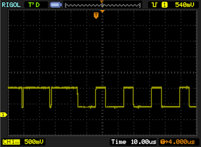
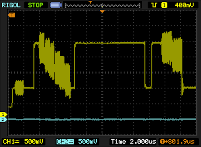
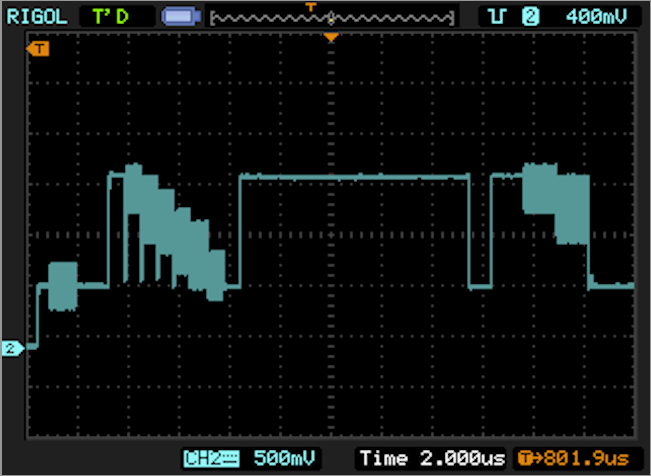
Yellow trace was AHD camera output on the 4 special lines:
Blue trace was my poor imitation (note the analog drive strength is higher from the camera, P2 has different levels):
Nice going.
Would a frequency meter help? I guess it would only help if well calibrated
1080p output on coaxial cable would be very useful in certain cases.
I'd definitely be in for 4k this way!
Thanks. Yeah it could help but only if you can setup a window/gate and test a signal that only occurs for a short period per scan line when you time it, otherwise external circuitry would be needed. I think the reverse engineering probably gives a usable outcome for now, until more is known.
I was able to get quite a bit further last night but was unable to post results due to network issues. One of my machines can't see parallax.com but my older machine is working albeit sluggish. Some machine or router reboot may be needed.
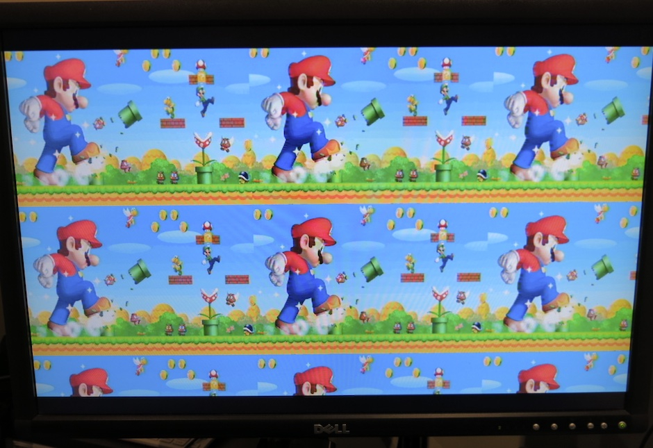
Here's 1080p25 AHD working with Chip's Mario pic I adjusted my video driver to replicate the image multiple times horizontally and vertically with its skew and wrap features because the image is only 720x480. It is sent using a 1920x1080p25 signal and converted to 1080p60 by the AHD to HDMI converter. It looks pretty decent on screen at first glance. A little softer than digital full HD of course but certainly usable.
I used using Chip's NTSC/PAL calculations to lock the subcarrier cycles per scanline to the total pixels per scanline which fixes the colour cycling.
In time I will likely merge this new capability into my video driver once I figure the proper set of changes to fully integrate it. The good thing is this should let me finally clean up the existing PAL/NTSC colour/timing quality as well which has been on the back-burner for ages. I have this work and some new parallel LCD code to go in (maybe with digital CGA/EGA support too, but that's not a priority). All this tidy up may end up possibly needing some changes to the timing structure I use (which @evanh has always wanted anyway).
That should be possible if the frequencies are something the P2 can generate, but perhaps with a different custom driver or more extensive changes. I think my current driver has a limit of up to 1920 pixels per line in LUT RAM IIRC. Need to check on that...