P2 Application Idea: Drive Step Motor with high Efficiency
Hi, some idea to use P2:
Normally step motors have very bad efficiency, because they are driven with maximum current, even if there is no load. (Like for example: https://ti.com/lit/an/slva416a/slva416a.pdf )
On the other hand they are easily available, have high torque and do not need position feedback. So if efficiency could be well improved, their use together with batteries would be attractive.
Idea:
Measure current and generated back EMV to influence the driving of the bridge. Increase current (PWM voltage), if the angle between magnetic field and rotor becomes too big and vice versa. To keep the position information, some surplus current shall be applied. No slip allowed. This type of driver is a hybrid between step motor driver and sensorless brushless driver.
P2 with it's lots of pins and ADCs might be be a good fit to the idea.
Probably the idea will not be new, so I am asking if someone can point to some good and understandable information/paper about something like this? Or have some other thoughts?
Christof


Comments
The most advanced solution I know is invented by Trinamic. Reading their documentation and the patents filed gives a good overview, how steppers can be optimized. But it doesn't work at standstill. A stepper needs current not to create torque, like other motors, the current is needed to create a potential barrier, with will, when the motor is displaced, create torque. So the only way out is: detect the displacement and then create the barrier in the right place at the required strength. This is an unsolved problem, as far as I know.
But trinamic is able to steer a running motor with minimal current and detect the very beginning of stall, increasing the current in time to prevent this stall. What also uses certified stepper motors.
Thanks, @ErNa , I will look if I can find some paper of trinamic! For many cases, a solution, which does not work at standstill will be fine. For example for self blocking threaded spindles, where you can simply shut off current. You can start the motor with bad efficiency.
I have found a paper about TI DRV8462, but they don't tell too much.
In: https://cds.cern.ch/record/2226506/files/tesis-Ricardo-Picatoste_2.pdf There is equation 2.2, which should enable the basic idea somehow, after K.m is known.
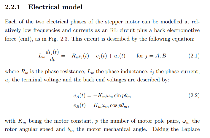
I wonder, if L.omega does not vary over the rotor angle?
Trinamic A popular ugrade for 3d printers because they are almost silent.
Not a fan of steppers. P2 has quadrature counting and with the low cost of encoders, today....Why not be sure that the motor(s) go to the intended position, not to mention having full control of motor torque (by limiting the motor command output) and all the other benefits of BLMs.
CUI is one of many kit-encoder sources.
A P2 Odrive would be nice
Rgds,
Craig
Hi Craig,
I do agree, that position feedback is nice to have for clean and fast solutions and sometimes just needed. Nevertheless cost can be an enabler for projects, that otherwise will just not happen. So let's have the focus in the direction of the basic idea in this thread. Perhaps P2's capabilities can trade for hardware.
I happen to have a low cost bridge driver module for 12V, 800mA. https://www.pollin.de/p/daypower-motorantriebsmodul-motor-9110-810572 I will see, if it is a good starting point.
Christof
Full Step Experiments - Yes, it works!
So I have started some experiments using full step mode. In this case at each step only one coil is active and the other one can be used as a sensor.
Setup:
Driver Bridge: L9110 Board with two of these chips
Motor: Small Motor Nema17 https://pollin.de/productdownloads/D310690D.PDFNo external load on the motor.
Current limited to 0.33A by 12V lab power supply.
P2:
Four Outputs to the 2 Bridge chips. One of these is PWM at each step the other ones are high.
One input from one end of one coil via a 22k resistor. The input voltage is limited by the pin protection diode. This signal is the same as the yellow trace on the pictures.
One DAC output to indicate the step and trigger the scope. - Pink trace.
The Motor has a relatively high winding resistance, which needs 10,4V to drive 0.33A. Not much left from 12V supply for speed.
There are protection diodes in the L9110 bridge chip, which connect each winding pin with +12V and with GND. There must be a internal resistor to GND too. So no negative voltage can be measured. And the voltage is limited to a little bit more than 12V.
The voltage at the coil is proportional the speed of the rotor.
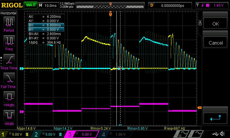
The first picture shows full step mode at step time 20ms, PWM 100%. We concentrate on step number 2 (from 0…3). Here the two ends of the inactive winding show first as blue peak the motion in the desired direction. Then we see the counter-movement as yellow voltage. Consecutive peaks show the declining oscillation around the new step position. The lab power supply showed about 0.29A.
Strategy with PWM
The strategy is now to start each movement with PWM=100% and to minimize the current (PWM percentage) as long as the counter movement can be detected in the yellow signal. Only step number 2 is used to vary the PWM percentage, which is nevertheless valid for all 4 steps.
Picture 2 shows the signal with the reduced power according to the strategy. The blue peak is less high and longer indicating lower maximum speed. The frequency of the oscillation is lower due to lower stiffness. The current consumption was reduced to 70mA at PWM=46%. If the bridge is turned off, the current consumption of the driver module module is still 33mA, so the motor is only driven here with about 40mA.
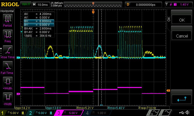
Picture 3 shows a reduced step time of 8ms. Now percentage is 63% and current is 80mA. The blue peak is higher than in picture 2.
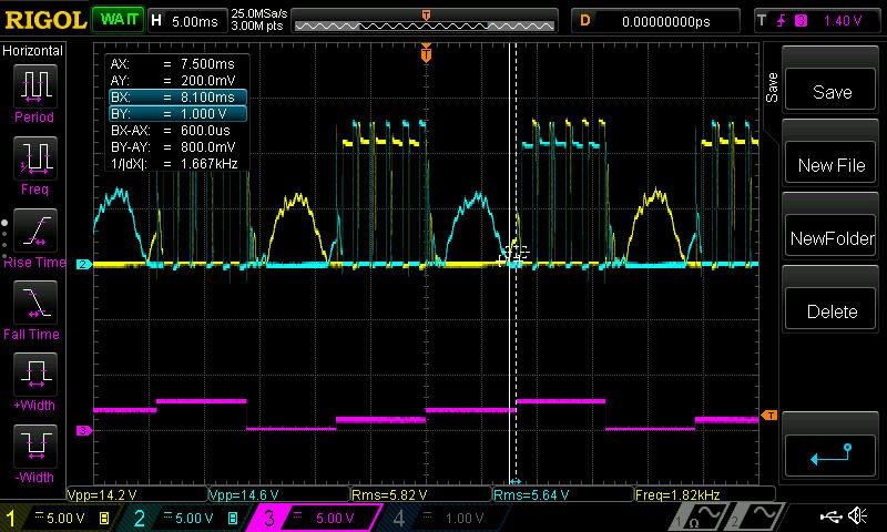
If the step time is reduced to about 5ms, there will no reduction of current any more. Just below 3ms the motor will loose steps.
Strategy with one solid single pulse for each step. Vary pulse length.
Here the strategy is, that a counter movement must be detected and the end of the counter movement must also be detected to reduce pulse length.
Picture shows step time 20ms. Active pulse length is 5.6ms. The maximum speed of the movement and the countermovement are higher with solid pulses than with PWM. Current consumption is very unstable at the lab power supply. Average should be 5,6/20*0,29=0,0812A.
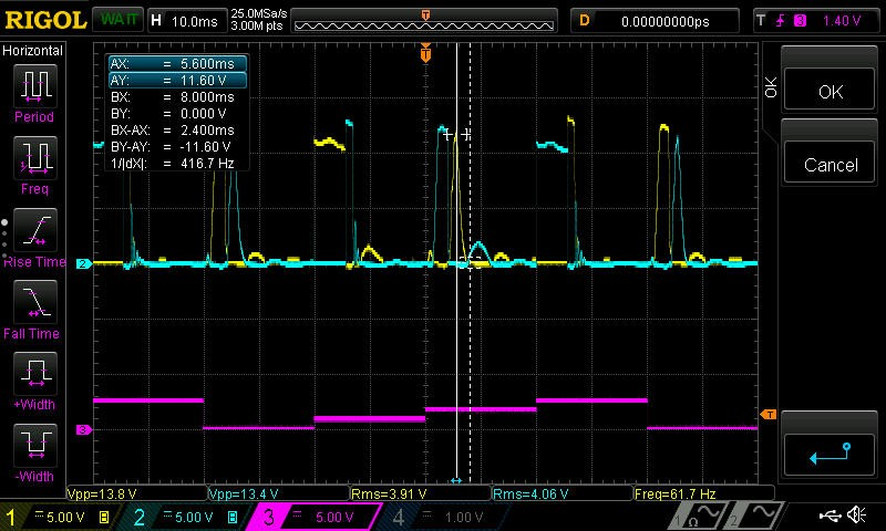
All in all, it seems to be possible to significantly reduce current consumption for slow movements with solid pulses or with PWM. Of course this has only effect, if the motor is only partially loaded. PWM worked somewhat better than solid pulses.
I wonder, if the solid pulses would enable half step mode somehow. At the moment I do not see, how micro stepping could be made possible.
Comments, suggestions?
Have fun!
Christof
P.S. I have attached my experimental Taqoz code as is.