

Call Button system for Movie Theater
 Luis_P
Posts: 246
Luis_P
Posts: 246
Hello! I have #124 seats with a call button in a movie theater. I'm wondering if it is possible to build my own system to show which seat is pressing the "call button" inside the auditorium. I will like to display on a monitor like "Seat: G12". I only have experience with Basic Stamp 2. Is there any micro controller with enough inputs to sense a "button press" ? or maybe daisy chain multiple micro controllers? any good ideas???? Thank you in advance!
Luis
Comments
Depending on the width of your rows, you might consider a micro per row/section that can scan a reasonable number of buttons. These could be on an RS-485 network that is scanned by a master controller, or even a PC program with an RS-485 interface. I think a P1 section controllers would be fine -- again, depending on inputs -- but those can easily be expanded with simple shift registers.
I have 13 seats per row. In Auditorium 1 total of 124 seats. Auditorium 2 the same. The other Auditoriums are small like 40 seats total 7 seats per row.
Do you intend on wiring buttons for each seat, you can go wireless but than you have to think about batteries, like those wireless doorbells that don't work. An easy solution would be an app for your customers phones, they could input their set number and ping you from the app.
Just for fun, I "sketched" an idea in my head that would allow 16 nodes of 16 inputs -- a total of 256 inputs; it gives you room to grow.
con { fixed io pins }

  PGM_RX   = 31  { I }                                          ' serial / programming
  PGM_TX   = 30  { O }

  EE_SDA   = 29  { I/O }                                        ' i2c / eeprom
  EE_SCL   = 28  { I/O }


con { app io pins }

  NODE_RX  = 27  { I }                                          ' RS-485
  NODE_TXE = 26  { O }
  NODE_TX  = 25  { O }

  STATUS   = 24  { O }                                          ' connected to host

  NC_23    = 23                                                 ' not connected
  NC_22    = 22
  NC_21    = 21
  NC_20    = 20

  ADDR_3   = 19  { I }                                          ' node address
  ADDR_2   = 18  { I }
  ADDR_1   = 17  { I }
  ADDR_0   = 16  { I }

  INS_MSB  = 15  { I }                                          ' 16 inputs (10k pull-down)
  INS_LSB  =  0  { I }
RS-485 is pretty easy and I've used it a lot with my friend/client John at JonyJib. I've attached my RS-485 driver for the P1. It has been used in many commercial apps.
We have a QR barcode on each table to order food. The “call button” is for customers having problems with their phones. We have buttons already wired. Wireless would be great but I can’t find a device that I can use with a PC (C # or V.Net software)
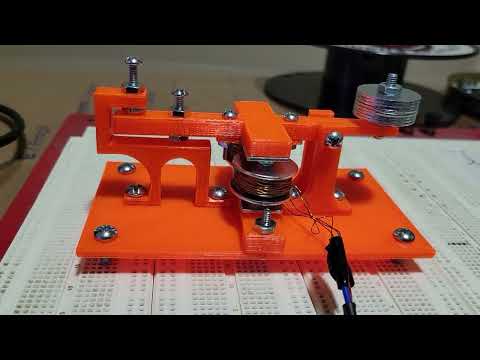
You need something like this a, PLC, this is my own prop version, has 16 inputs for buttons and 16 outputs, but I could make it 32 inputs etc. this version has VGA, keyboard, mouse, RS232, etc. basically a mini PC.
There are many ways to approach this ... first of all I should ask ... "What is your budget?"
The wireless approach is the cleanest, but perhaps more costly.
You say the switches are already wired.... you could repurpose that wiring and just supply power to the "wireless units" ... ahem, so they are wired. :-)
Each wireless unit would have a unique address and could communicate over a private network as a Client.... think headless web page that submits form data to a Server. The Server could be a Python program, Perl program, whatever that logs data and or presents the data to a display located on a PC, Linux, etc.
The "micro on every row" might work, but that's a lot of wire maintenance to deal with as far as troubleshooting.
In this case each micro would function as a Slave and have it's own unique ID.
The PC,Linux, etc. would function as a Master and periodically poll the Slaves.
When a Slave "sees" it's address then it responds with the switch data for that row.
Note: In either case I would strongly recommend using a CRC of some kind between any of your data transfers.
Agreed. We do that with packets in JonyJib products because we're controlling expensive cameras on the remote side.
Already wired to where ?
Usually you choose the scan, and approach, to lower the cabling cost, so you tend to use a number of low cost MCUs.
If you are cabling-cost and size focused, you can use RS485 or similar over power cabling
https://www.ti.com/lit/pdf/tidu993
You can also 'compress' multiple buttons into one MCU pin, if that has a good ADC (10b or 12b) & you need a design that can sense any/all buttons, not just one-of-N, so 4~5 buttons per pin is a practical target.
https://forums.parallax.com/discussion/172874/multiple-pushbuttons-on-one-pin-using-adaptive-adc/p1
Lots covered there, a fully passive design where RL=(string sum) has a LSB step for 5 R of 0.819%, so it's heading to marginal with high volume resistors.
If you can arrange a 1% current source, a current-fed R has a LSB of ~ 3.14% with the same 5-Rstring.
These days, a 1% LDO with low/stable IQ can give a precision current source. (maybe AP7380, or NCP730 )
If you are cabling, a 'switch across a resistor' wiring allows a simple string, over 4-5 seats, but you need care to replace any failed node with the same resistor value.
There is wiring already because there was a system in place before that we discontinued. So we have wires on all buttons going to a unit in the row that has been removed.
Then you will likely want to clone your new system to scan the same way that was all wired.
Do you have a wiring diagram for the button matrix needed ?
You can use 'upgraded' shift register parts like xPIC6C595 to give scan of one side of matrix.
I have decided to use a Basic Stamp to detect 13 button press and send the data to a XBee/XBee to PC. Wish me luck! 😊
Looks like you'll need at least 10 ea. Bs2's and Xbee's
Yes! On each row. We have 7 auditoriums so it is a big project!
Don't forget you'll run +5 VDC out of the BS2 board to each button and back, how many feet? Careful of voltage spikes back to the Pin.
Isn’t the resistors used for a button press (shown on BS2 button press example) protects the pin? How many feet? From where to where? Is that matters?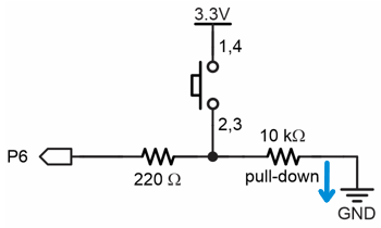
Bs2 will be 5VDC, 3.3V is for the propeller. If you use 3.3v you may get too much voltage drop. But your schematic should work. Don't subject any pin to more than 100 Milliamp current.
However the PIC16F57 does have an operating range of 2.0-5.5 Vdc. But I think the BS2 brown out detectors cuts out at 4.2 Volt
Luis_P,
On the BS2, we usually connect switches to the Vdd pin which is 5V.
The 220 Ohm is a current-limiting resistor so the I/O pin won't fry if 5V should go straight into it.
The 10K resistor allows a small amount of current to flow so the I/O pin will be 0, but the switch will easily pull it to 1 when pressed.
Correct!! @DigitalBob Said to be careful with the voltage spike but with circuit in the BS2 manual should not be any issues right?
No matter what processor you use, you'll want to debounce your inputs so that electrical noise doesn't create a false positive.
Im getting confused now. My question is: the circuit I posted is correct? Or I have to add something else to the circuit?
That circuit is fine, but you need to scan the buttons in such a way that a noise pulse on an input doesn't create a false trigger. Lets say, for example, you decide to use pins 0..7 as inputs. Humans are slow, so I would debouce the inputs for ~25ms like this
Scan_Buttons:
  btnIns = %11111111                            ' arm all inputs
  FOR x = 1 TO 25                               ' must press for >= 25ms
    PAUSE 1                                     ' hold
    btnIns = btnIns & INL                       ' apply current state
  NEXT
  RETURN
Even though the BASIC Stamp is slow by modern standards, if you do something simplistic like this:
without debouncing, you could get false positives. I've seen this in the real world at a Haunted House that used a bunch of BS2s to control props. Their trigger code didn't use any debounce, so occasional radio transmissions would trigger props when not intended.
Yes! I remember that! Done it before. Thanks for reminding me
Wires? 2023?
I'd be looking at this....
https://novelbits.io/bluetooth-mesh-networking-the-ultimate-guide/
Craig
This is my debounce on the RPi Pico. Must have 8 identical reads over (in this case) 40ms.
SetPin GP2, DIN, PULLUP
SetPin GP3, DIN, PULLUP
SetPin GP4, DIN, PULLUP
SetPin GP5, DIN, PULLUP
SetPin GP6, DIN, PULLUP
SetPin GP7, DIN, PULLUP

portread% = 0
filtered% = 0
scan_period% = 5
scan_count% = 0
settick scan_period%, scanin  'Read the port every 5ms

do
    if scan_count% > 7 then 'State of port hasn't changed for at least 8 scans

        if filtered% and not 1 then print "2"
        if filtered% and not 2 then print "3"
        if filtered% and not 4 then print "4"
        if filtered% and not 8 then print "5"
        if filtered% and not 16 then print "6"
        if filtered% and not 32 then print "7"
        scan_count%=0
    end if
loop

sub scanin

if scan_count% = 0 then
    portread% = port(gp2,6)
    inc scan_count%
elseif portread% <> port(gp2,6) then
    scan_count% = 0
else
    inc scan_count%
    if scan_count% = 8 then
        filtered% = portread%
    end if
end if

end sub
Craig
@ Mickster "Wires? 2023?" - I mean technically you could use nothing but ESP8266 in a point to point access mode. No need for a Wifi hot spot... in a sense it is a WiFi mesh.
I did something similar for a wireless Morse code transponder I did for a demo at a HAM radio conference with about 4 transponders. I tested the distance at about 350 feet. The ESP8266's were programmed in a bidirectional mode. Only one ESP8266 per transponder. ALL ESP8266's are capable of transmitting as well as receiving.
Receiver:
Right now you can get 5 ESP8266's on Amazon with the USB serial connection for $13.99 or 5 ESP8266's for $10.88 without the USB serial connection.
@"Beau Schwabe"
Think I might pick-up a few of these to play with. Should be able to run standalone, right?
"Deep sleep" current draw seems pretty good:
https://rfsolutions.co.uk/radio-modules-c10/ble-bluetooth-mesh-module-5-2-dip-18-package-p993
Craig
I would do this for about USD$5 per seat (for the electronics) using ESP8266 ESP-01 modules and the wireless WiFi-based ESPnow protocol. You would still have to do batteries or wire power to all the stations, but that's a lot easier than doing a 100+ node data network. The ESP can only register about 20 ESPnow peers, so you would probably want to equip each row with a "row master" that registers all the seats and the master node that collects all the data. The master node would only need to register the row masters. The ESP01 is extremely cheap and small and has a couple of GPIO inputs broken out that you can use for pushbuttons. You can't wake up an ESP01 from deep sleep (GPIO16 isn't brought out to the 8-pin header) but you can turn off the WiFi system to save a bit of power until a button press. Everything in ESPnow is peer to peer and defined by MAC addresses so it's easy to cram 100+ nodes in a room without having them interfere with each other. I could probably put a system like this together in a day or so. Just an idea...