@Rayman said:
OPNAcog VGM sounds like some kind of torture test?
No, just one two cogs going at 320 MHz.
I think that PFM stuff is just for low current mode. I don't think that's relevant in your tests...
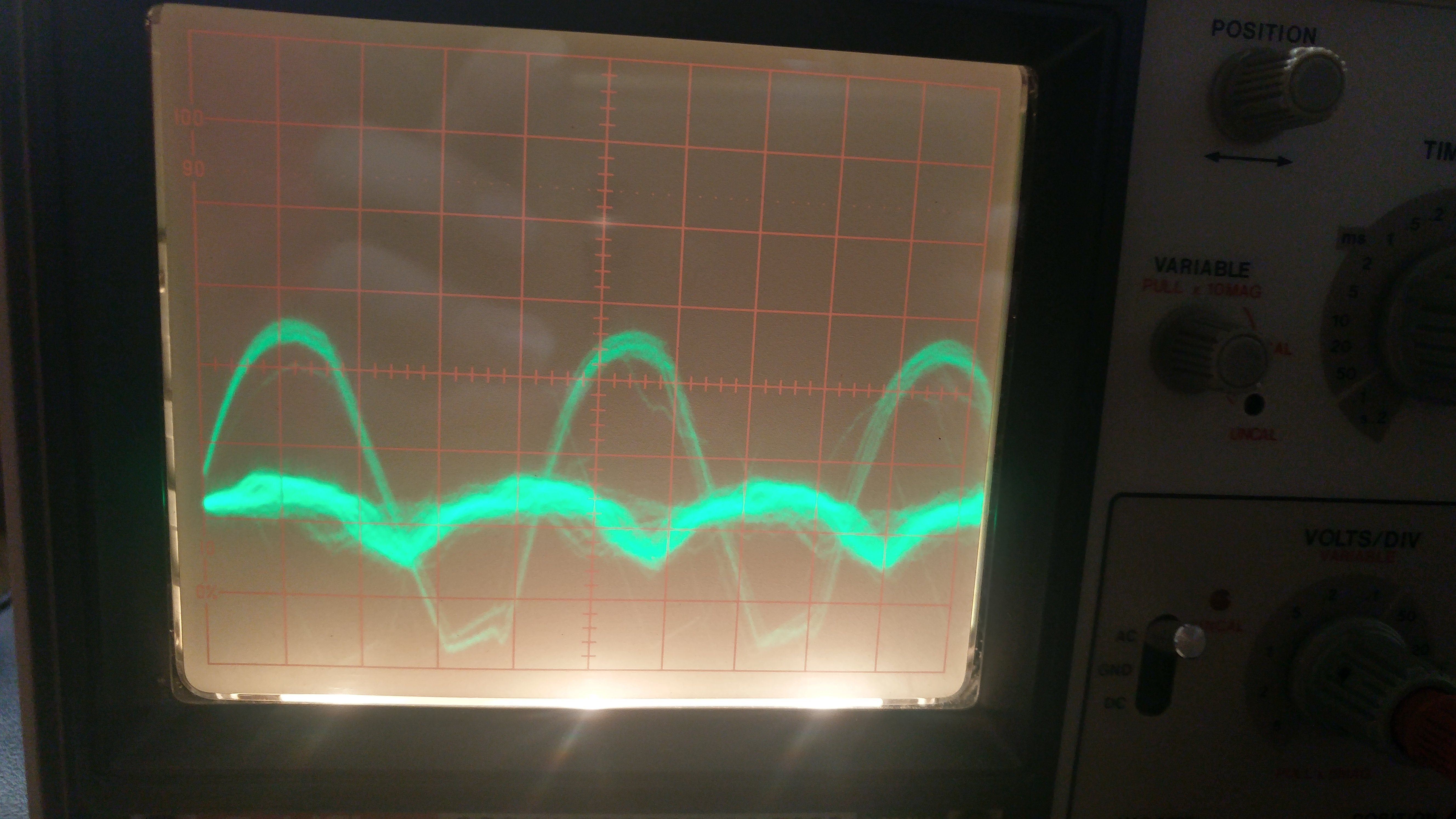
I'm pretty sure it is PFM mode. The waveform looks about right and it does infact go away when running NeoYume on the board with audio.
BUT HERE'S A WHACK ONE: The board without the amp (i.e. our most reliable one) switches back and forth!
(The smaller waveform is identical to the audio board and appears to be related to the video signal (why ??? RAM power? - must be, frequency is close to 16kHz and this is VGA 3x mode))
I can certainly try the other version of regulator to see if helps with audio.
This may not be the best board for analog but hopefully can be improved.
Hoping that either 10uf or 0.1uf caps on all the vio using pads under the board will clean it up.
@Rayman said:
I can certainly try the other version of regulator to see if helps with audio.
Though that one allegedly has a minimum current without which it isn't able to regulate. Maybe there's a part out there that's just overall better. Going with the Parallax-style intermediate fat switcher + multiple LDOs seems like a good idea, that just works.
From my testing adding the 100uF capacitor on wires only helps a little. If you can hear it, the frequency is already very low, so hard to filter. Though the video-induced noise isn't nearly as bad as the regulator whine noise.
Also, just testing some more on the other board: Regulator switching modes sounds like a geiger counter going off. Megayume is just on the edge of where it switches. So I guess the 500mA spec is fine. Or maybe having a fatter regulator is just to make it more stable?
Huh, lol, I'd never bothered to read the specs on the Eval Boards. It seems I've managed to pull more current than the rated 2.0 Amps ... looking up a datasheet ... ah, can be explained with current limit at about 3.0 Amps for the TPS62902. EDIT: And the AP2445 doesn't explicitly state a limit but looks like it's in excess of 4.0 Amps.
It may take a little fan to keep it going. Have mixed results there. Some can go for hours just fine. One definitely needs a fan to go more than a few minutes.
The whole board does get warm when running NeoYume for a long time...
The new stencil is going to have more paste under the P2. I'm hopeful this will improve the situation.
I do have fins that I tried earlier with the 2-layer version. Didn't help.
But, might be worth looking at those again to see if it helps.
Seems to me fins are only really going to work when combined with forced air, but maybe I'm wrong...
There's also a question about how to attach fins. Guessing that needs the CPU grease. That's a bit messy though, especially on top of the chip...
@Rayman said:
I do have fins that I tried earlier with the 2-layer version. Didn't help.
But, might be worth looking at those again to see if it helps.
Seems to me fins are only really going to work when combined with forced air, but maybe I'm wrong...
There's also a question about how to attach fins. Guessing that needs the CPU grease. That's a bit messy though, especially on top of the chip...
I was meaning underneath, if PCB mounting allows the room ?
If you need lower profile, I see Aliexpress have copper fins 13x12 x 4/5/7mm
Addit : since your PCB looks to be quite large at ~ 100mm, there are 100mm heat pipes, thin and wide enough to cover P2 solder landing.
(needs a gentle wave bend to clear the caps ? ) It could transfer heat to a metal case.
Advanced Thermal Solutions Inc. Manufacturer Product Number ATS-HP-F7L100S70W-016 Description FLAT HEATPIPE 70W 3.5X11.2X100MM
You could compare different PSRAM delay test runs with the different bank chip select pins to see if delay crossover frequency breakpoints are the same or offset significantly between banks. If they are behaving quite differently around the frequency you are operating at then you'll want to configure different delays for each bank, although I sort of doubt it would be that bad. My low level COG code can support doing that, because these input delays are associated with each 16MB boundary, although I'm not sure if NeoYume still assumes a common delay over the entire PSRAM address space or not these days (it might).
@rogloh said:
You could compare different PSRAM delay test runs with the different bank chip select pins to see if delay crossover frequency breakpoints are the same or offset significantly between banks. If they are behaving quite differently around the frequency you are operating at then you'll want to configure different delays for each bank, although I sort of doubt it would be that bad. My low level COG code can support doing that, because these input delays are associated with each 16MB boundary, although I'm not sure if NeoYume still assumes a common delay over the entire PSRAM address space or not these days (it might).
No per-bank delay compensation. Would add a hot bunch of instrs into the mix, not terribly bad, but I'd prefer not to because it'd create a big mess in the code (many config constants, awful expressions to precompute lookup tables). But if these boards need it at sysclk/3 and none of the other setups need it at all, I think that just means these boards have a problem.
On the bad boards you could also possibly setup a smartpin to output some fixed frequency on a pin and keep an eye on the jitter using a delayed trigger on a scope when running NeoYume and loading up the P2, in case it's a PLL noise type of problem. If you have a lot of jitter it could potentially mess up some PSRAM reads given that the input delay needed for a valid setup time should remain stable and not vary (as it would do if you had jittery clock cycles on the P2).
Some good ideas. There isn't any exposed 1.8 V pin though. Clock jitter, maybe. There's some kind of jittering in the VGA output, haven't mentioned it in this thread, where the edges that the monitor doesn't cleanly sample (because in 3x mode it tries to sample 1024px but we do 320px) are slightly shifty.
Currently have been running a game that fits into a single bank for a while without issue... So that's interesting.
There is kind of a test point for 1.8V... Under the big 5V linear regulator are the two switching regulators.
To the left of each are the inductors for them. Just to the left of those are large vias that can be used as test points.
The lower one is 1.8V.
But, what may be more insteresting is the voltage closer to the chip. THere is a ring of capacitors around the chip with either other one being 1.8V. There are small vias on either side. One closer to the chip is the 1.8V side, other side ground.
second-bank hack still going strong after ~4.5 hours. big if true ( I HAVE NO IDEA WHY THIS WOULD WORK )
Will probe around with the vias after that experiment concludes. Sadly not hook compatible (I always have anxiety about poking around while the power is on...)
@Wuerfel_21 Did both banks when run independently use the exact same timing? Maybe one bank has somewhat worse performing PSRAM chips, or the fact that both banks are active more often somehow requires more power or creates more noise on the supply? A little strange but if you don't initialize some of the PSRAMs perhaps these extra chips are in a sleep state and don't consume too much power...?
First unit from new stencil works! Kind of relieved. I also added 10uF caps under the board to see if it helps audio.
Problem is that I'm not sure I can tell the difference between Eval board and my board audio...
Is there a particular game where it's easy to tell?
One thing I am seeing is a very large difference in volume between Eval board and my board. My boards are much louder.
This has me a bit puzzled as the circuits are exactly the same.
Only thing I can think of is the ESR of the series caps. The Eval caps are 0603 and mine are 0805. But, not sure if that's the difference.
Seems voltage rating and material used also make a difference.
I found this web tool that shows ESR and it's pretty bad at audio frequencies:
@Rayman said:
First unit from new stencil works! Kind of relieved. I also added 10uF caps under the board to see if it helps audio.
Problem is that I'm not sure I can tell the difference between Eval board and my board audio...
Is there a particular game where it's easy to tell?
Anything where there's a static screen with no actual sound. You can then hear all the background noise. Also, the aforementioned OPNAcog, I'm sure sent you the binary at some point. That one has the awful PFM whine. Should probably also bundle up some workable example for the heptafon player, that one is also quite bad (SD card access...)
Thanks for reminding me of ExampleVGMPlay.binary
Think am noticing a high pitch whine that starts at beginning of audio. Hard to tell later because there's actual notes at a nearby frequency.
But, can tell at the start.
I have one of ~4 boards that don't have this. New one does have the whine
Did have to rework this chip, maybe something is off...


Comments
No, just one two cogs going at 320 MHz.
I'm pretty sure it is PFM mode. The waveform looks about right and it does infact go away when running NeoYume on the board with audio.
BUT HERE'S A WHACK ONE: The board without the amp (i.e. our most reliable one) switches back and forth!
(The smaller waveform is identical to the audio board and appears to be related to the video signal (why ??? RAM power? - must be, frequency is close to 16kHz and this is VGA 3x mode))
(also, each board has a different amplitude of this larger ripple waveform)
I can certainly try the other version of regulator to see if helps with audio.
This may not be the best board for analog but hopefully can be improved.
Hoping that either 10uf or 0.1uf caps on all the vio using pads under the board will clean it up.
Though that one allegedly has a minimum current without which it isn't able to regulate. Maybe there's a part out there that's just overall better. Going with the Parallax-style intermediate fat switcher + multiple LDOs seems like a good idea, that just works.
From my testing adding the 100uF capacitor on wires only helps a little. If you can hear it, the frequency is already very low, so hard to filter. Though the video-induced noise isn't nearly as bad as the regulator whine noise.
Also, just testing some more on the other board: Regulator switching modes sounds like a geiger counter going off. Megayume is just on the edge of where it switches. So I guess the 500mA spec is fine. Or maybe having a fatter regulator is just to make it more stable?
My ancient power test program needs greater than 2.5 Amps on 1.8 Volt supply when overclocked. See Roger's experience - https://forums.parallax.com/discussion/comment/1528469/#Comment_1528469
This may not fill the void when edge is gone. Good enough for any practical application I can imagine.
Do need to pay more attention to audio though. Don’t want that to be horrible …
Oh, if that's true, how is it even running at all :P So do upgrade to 3A regulators.
I should buy one of those USB power meters...
Huh, lol, I'd never bothered to read the specs on the Eval Boards. It seems I've managed to pull more current than the rated 2.0 Amps ... looking up a datasheet ... ah, can be explained with current limit at about 3.0 Amps for the TPS62902. EDIT: And the AP2445 doesn't explicitly state a limit but looks like it's in excess of 4.0 Amps.
Also, long-term test results are in and it seems that even in slow sysclk/3 mode, the boards still crash after a few hours.
It may take a little fan to keep it going. Have mixed results there. Some can go for hours just fine. One definitely needs a fan to go more than a few minutes.
The whole board does get warm when running NeoYume for a long time...
The new stencil is going to have more paste under the P2. I'm hopeful this will improve the situation.
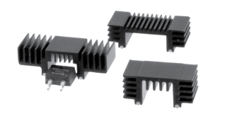
Since this is close, you could try one of those solder on fins underside, made for cooling d/ddpak parts ?
I do have fins that I tried earlier with the 2-layer version. Didn't help.
But, might be worth looking at those again to see if it helps.
Seems to me fins are only really going to work when combined with forced air, but maybe I'm wrong...
There's also a question about how to attach fins. Guessing that needs the CPU grease. That's a bit messy though, especially on top of the chip...
Crash may only be when using the second PSRAM bank. Maybe timing settings are not quite OK? Or maybe board really is that unhealthy...
I was meaning underneath, if PCB mounting allows the room ?
If you need lower profile, I see Aliexpress have copper fins 13x12 x 4/5/7mm
Addit : since your PCB looks to be quite large at ~ 100mm, there are 100mm heat pipes, thin and wide enough to cover P2 solder landing.
(needs a gentle wave bend to clear the caps ? ) It could transfer heat to a metal case.
Advanced Thermal Solutions Inc. Manufacturer Product Number ATS-HP-F7L100S70W-016 Description FLAT HEATPIPE 70W 3.5X11.2X100MM
You could compare different PSRAM delay test runs with the different bank chip select pins to see if delay crossover frequency breakpoints are the same or offset significantly between banks. If they are behaving quite differently around the frequency you are operating at then you'll want to configure different delays for each bank, although I sort of doubt it would be that bad. My low level COG code can support doing that, because these input delays are associated with each 16MB boundary, although I'm not sure if NeoYume still assumes a common delay over the entire PSRAM address space or not these days (it might).
No per-bank delay compensation. Would add a hot bunch of instrs into the mix, not terribly bad, but I'd prefer not to because it'd create a big mess in the code (many config constants, awful expressions to precompute lookup tables). But if these boards need it at sysclk/3 and none of the other setups need it at all, I think that just means these boards have a problem.
It might pay to put the scope probe on the 1.8 V supply rail. Measure idling and measure again with NeoYume in full swing.
On the bad boards you could also possibly setup a smartpin to output some fixed frequency on a pin and keep an eye on the jitter using a delayed trigger on a scope when running NeoYume and loading up the P2, in case it's a PLL noise type of problem. If you have a lot of jitter it could potentially mess up some PSRAM reads given that the input delay needed for a valid setup time should remain stable and not vary (as it would do if you had jittery clock cycles on the P2).
Some good ideas. There isn't any exposed 1.8 V pin though. Clock jitter, maybe. There's some kind of jittering in the VGA output, haven't mentioned it in this thread, where the edges that the monitor doesn't cleanly sample (because in 3x mode it tries to sample 1024px but we do 320px) are slightly shifty.
Currently have been running a game that fits into a single bank for a while without issue... So that's interesting.
Hmm, version I hacked to run on second bank only is still running. Still has to go longer to be conclusive, but that sure is interesting.
There is kind of a test point for 1.8V... Under the big 5V linear regulator are the two switching regulators.
To the left of each are the inductors for them. Just to the left of those are large vias that can be used as test points.
The lower one is 1.8V.
But, what may be more insteresting is the voltage closer to the chip. THere is a ring of capacitors around the chip with either other one being 1.8V. There are small vias on either side. One closer to the chip is the 1.8V side, other side ground.
second-bank hack still going strong after ~4.5 hours. big if true ( I HAVE NO IDEA WHY THIS WOULD WORK )
Will probe around with the vias after that experiment concludes. Sadly not hook compatible (I always have anxiety about poking around while the power is on...)
Did eventually crash but now it's quite late.
Also, no, neither of the normally adjacent timings works.
as perhaps expected
does boot though, so I guess that's what we're running over night.
@Wuerfel_21 Did both banks when run independently use the exact same timing? Maybe one bank has somewhat worse performing PSRAM chips, or the fact that both banks are active more often somehow requires more power or creates more noise on the supply? A little strange but if you don't initialize some of the PSRAMs perhaps these extra chips are in a sleep state and don't consume too much power...?
16/async/async still going as of now.
First unit from new stencil works! Kind of relieved. I also added 10uF caps under the board to see if it helps audio.
Problem is that I'm not sure I can tell the difference between Eval board and my board audio...
Is there a particular game where it's easy to tell?
One thing I am seeing is a very large difference in volume between Eval board and my board. My boards are much louder.
This has me a bit puzzled as the circuits are exactly the same.
Only thing I can think of is the ESR of the series caps. The Eval caps are 0603 and mine are 0805. But, not sure if that's the difference.
Seems voltage rating and material used also make a difference.
I found this web tool that shows ESR and it's pretty bad at audio frequencies:
Anything where there's a static screen with no actual sound. You can then hear all the background noise. Also, the aforementioned OPNAcog, I'm sure sent you the binary at some point. That one has the awful PFM whine. Should probably also bundle up some workable example for the heptafon player, that one is also quite bad (SD card access...)
Thanks for reminding me of ExampleVGMPlay.binary
Think am noticing a high pitch whine that starts at beginning of audio. Hard to tell later because there's actual notes at a nearby frequency.
But, can tell at the start.
I have one of ~4 boards that don't have this. New one does have the whine
Did have to rework this chip, maybe something is off...