New layout with two bolt holes through the PCB near opposite corners of the Prop2. These can then be used to mount a heat-sink either on top or underneath.
EDIT: Mount a thin heatsink both sides so no torquing the PCB then.
Made two boards this weekend with thin stencil
First one won't run NeoYume, as usual. Just get black screen.
Second one though had some extra paste added under the P2.
This time the P2 stayed in position (last time I tried this the P2 shifted position in a bad way).
This one runs NeoYume and is fully populated.
However, it needs a small fan on it to run NeoYume for more than a couple minutes.
Maybe a heatsink would work as well.
I'm more optimistic about the design now. Thinking the audio issue was some kind of fluke.
Now have two boards with A/V and USB that are what I'll call fully good:
No.2 from thick stencil runs NeoYume without any cooling.
No.6 from thin stencil (with added paste under P2) runs NeoYume but needs small fan on it to go more than a couple minutes.
@Rayman said:
Back to thinking stencil thickness is the key.
I just found the gerbers to examine the layout:
You've got a serious thermal barrier on the bottom layer. The ring of capacitors is cutting off the dissipation path. The Eval and Edge boards certainly solved this with the caps all placed on the top layer instead. I guess that's why the signals all ended up in a middle layer with them. Which should also make the analogue quieter. I'd probably try merge the two existing middle layers - to make room for that middle signal layer.
An alternative might be leave the via grid exposed on the bottom, like the Prop2-Stamp. Allowing for a heatsink attachment.
I don't think thermals are the problem. The Stamp gets really, really hot. Hurts to touch the P2 chip. This doesn't get anywhere near that hot. So the thermals are working good enough I feel. Real issue to focus on is why the RAM is so flaky. (And aforementioned analog A/V interference issues)
The other possibility would be to switch to a different memory that may actually be rated for the speeds we drive it. I think there's a single-chip 3 volt 64MB HyperRAM now (IS66WVH64M8DBLL).
Though idk how the performance would actually compare to sysclk/3 PSRAM. HyperRAM has loooong setups.
Maybe suboptimal power + suboptimal layout + random chip variation wrt to overclockability. Reminder that these all seemingly work at slightly lower sysclock used by megayume.
I would say so. Working sysclk/3 setting means the P2 core isn't having thermal issues. Though the RAMs can have thermal issues, too, I think. My 96MB EVAL setup stopped working reliably after a while of running in the heat outside for a while (a few weeks ago when it was really hot). That affected one bank only I think. Anyways, don't think that's it because it fails immediately on cold boot.
There seem to be two thermal issues. One where NeoYume won't even start. Chip itself is still cold. Another one where NeoYume freezes after several minutes. Was able to fix that with a little fan.
I've made several boards (around 6, I think) with the 5-mil stencil and none of them work for NeoYume, won't even start it.
Guess I can't prove the stencil thickness is the issue yet.
But, I just bought a 7-mil stencil and that will hopefully put this to rest.
@Wuerfel_21 Thanks for telling me about the audio and video noise. As @evanh pointed out, I have place on the bottom of the board for an extra capacitor for every supply pin.
Wasn't planning on populating it, but maybe I should... Guess question is whether to use big C or little C there...
Ideally you'd have a separate VIO rail for the AV section, I think?
Anyways, I don't think the cold issue is infact a thermal issue. Maybe it is power, too? What's the tolerance on those regulators? Maybe it's a supply voltage issue. That would explain why adding the amp chip made the board more flaky. It consumes power and causes the VIO rail to drop. Clocking the RAMs so high might require a voltage more towards the higher end of the allowed range. This is how PC DDR memory achieves its peak perfomance afterall, wherein the motherboard has adjustable regulators to dial in the right voltage as specified by the RAM module's EEPROM. I'll compare the VIO levels on this board with the Edge and Eval. There might be something to that.
Call me crazy but the worst board has the lowest in-game VIO and also the highest difference between menu and in-game...
Caveats:
All tests made with neoyume running Twinkle Star Sprites in sysclk/3 mode
SimpleP2 boards all tested with 100uF capacitor added, just because the legs of that are easier to measure without causing a short
Can't meaningfully test P2 EDGE because the relevant rails aren't exposed
All measurements by my ancient and terrible meter (and thus only 3 digits)
I don't have a bench power supply (and a precise one at that), but if I did, I would try setting it to 3.4 V (which is in acceptable range for P2 and RAMs) and try to run a board with the instant-crash issue off that. Would need to set DIRECT_BOOT since in absence of the 5V rail we can't control the game menu.
An oscilloscope is needed to check what, in reality, is going on with this VIO voltage. This 0.04 V drop is not relevant, but the meter averages what it gets. There may be short pulses of voltage low or high enough to make things working bad.
Possibly, yes. I'd have hoped for more decisive values. PC RAMs get about 0.1 to 0.2 more than usual when running in "extreme" mode, so that's what I was coming from. As mentioned, the Simple boards were measured with fat capacitor added. I only have an analog scope (whose calibration I don't really trust), so not sure how useful that'll be.
@Rayman said:
@Wuerfel_21 Thanks for telling me about the audio and video noise. As @evanh pointed out, I have place on the bottom of the board for an extra capacitor for every supply pin.
Wasn't planning on populating it, but maybe I should... Guess question is whether to use big C or little C there...
Oh? Oh! Second look and I see now you've duplicated the caps from the top. Oh-oh, and third look you've got pin6, the SCLK pins, of the PSRAMs going to ... pin P30 .... eek! Even using an oscillator module might not be good enough in this setup.
You want to be supporting that V2831 power rail to keep XIN as clean as possible, and ditch the crystal for a module if you haven't already. Better still, move the SCLK well away, say up at pin P48. And may as well move the other three on pins P28..P31 too.
@evanh said:
Oh? Oh! Second look and I see now you've duplicated the caps from the top. Oh-oh, and third look you've got pin6, the SCLK pins, of the PSRAMs going to ... pin P30 .... eek! Even using an oscillator module might not be good enough in this setup.
You want to be supporting that V2831 power rail to keep XIN as clean as possible, and ditch the crystal for a module if you haven't already. Better still, move the SCLK well away, say up at pin P48. And may as well move the other three on pins P28..P31 too.
I think I noted that a while back as well...
@rogloh said:
Hopefully the choice to use P28-P31 for the control lines and high speed clock won't come back to bite you later. If it were me I'd have used P48-P51 for those signals to not mess with the PLL IO supply on that nibble.
Another idea is if you have a known bad board that fails and some spare PSRAMs, maybe you could solder a new set of them in and see if they help, assuming you are willing to potentially waste these if you can't reuse them later. Better of course to try to first pinpoint which RAMs are slower and failing at high speeds so you just swap those ones out. My delay test can be configured to show the first data error results which may help identity which nibbles are bad. Also do bear in mind this is still overclocking PSRAMs so not all manufactured PSRAMs might be capable of running NeoYume, even though I think most of the parts I've used seem to be capable of high speed operation at this frequency at least with P2-EVAL in my experiments when you don't have the high fanout.
Another possible improvement for new boards that I was just reminded of: Since the SD pins are already non-standard, maybe make the full 4 bit pinout available. @evanh was working on a driver, so I guess he can illuminate us on the ideal pin arrangement.
@Wuerfel_21 said:
Another possible improvement for new boards that I was just reminded of: Since the SD pins are already non-standard, maybe make the full 4 bit pinout available. @evanh was working on a driver, so I guess he can illuminate us on the ideal pin arrangement.
In the absence of any better pinout the pin mapping I came up with should work okay if you can afford 8 pins for SD. This pinout worked for me at the time I messed with it (no writes there yet either but I don't see an issue with that). It does burn two additional pins over the raw 6 needed for 4 bit SD mode but for that you get card power on/off (which is really needed for full SD card reset reliability) and a card detection feature plus a useful activity LED. Also these extra two pins can potentially do double duty as smartpins that are both within a working distance of the CMD pin. I think Evan may have already made use of that at some point.
I managed to get it to also still support SPI mode, albeit with some flexspin driver tweaks evanh mentioned were needed after some optimization he added. I'd expect supporting SPI mode as well is still probably somewhat important for codebases where you don't have an SD driver. E.g. running something like native micropython for example.
@rogloh said:
I managed to get it to also still support SPI mode, albeit with some flexspin driver tweaks evanh mentioned were needed after some optimization he added. I'd expect supporting SPI mode as well is still probably somewhat important for codebases where you don't have an SD driver. E.g. running something like native micropython for example.
Ha, had to scratch my head on recovering that from dusty memories - Used a serial rx smartpin half way between the CLK and DAT0(MISO) pins to get enough reach out of the +-3 pin input range.
PS: That was only a hack. I never submitted it to Eric.
EDIT: Hmm, on second thoughts, I seem to have made it robust enough. Maybe I could send it Eric's way after all ...
Hmm, I just looked at the datasheet and it seems the regulators for the 1v8 and 3v3 rails are only specced for 500mA output current. The Edge module has 3A capacity for 1v8 and 300mA per pingroup (so 2.4A total) for VIO.
I have a program (OPNAcog example) that causes the regulators and associated coils to whine their heart out. It's amplified on the audio out, but I can hear it even just putting my ear near the board.
Though in my testing with NeoYume, the whine sometimes goes away... Need to see if I can get that on scope. Maybe that's the regulator switching between its PFM and PWM modes? The datasheet alleges that there's a -B version of the device that doesn't have the PFM mode to avoid it's ripply nonsense.
OPNAcog VGM sounds like some kind of torture test?
I'm wondering if 10 uF caps on the bottom of the board will help with the audio situation.
I think that PFM stuff is just for low current mode. I don't think that's relevant in your tests...


Comments
New layout with two bolt holes through the PCB near opposite corners of the Prop2. These can then be used to mount a heat-sink either on top or underneath.
EDIT: Mount a thin heatsink both sides so no torquing the PCB then.
Back to thinking stencil thickness is the key.
Made two boards this weekend with thin stencil
First one won't run NeoYume, as usual. Just get black screen.
Second one though had some extra paste added under the P2.
This time the P2 stayed in position (last time I tried this the P2 shifted position in a bad way).
This one runs NeoYume and is fully populated.
However, it needs a small fan on it to run NeoYume for more than a couple minutes.
Maybe a heatsink would work as well.
I'm more optimistic about the design now. Thinking the audio issue was some kind of fluke.
Now have two boards with A/V and USB that are what I'll call fully good:
No.2 from thick stencil runs NeoYume without any cooling.
No.6 from thin stencil (with added paste under P2) runs NeoYume but needs small fan on it to go more than a couple minutes.
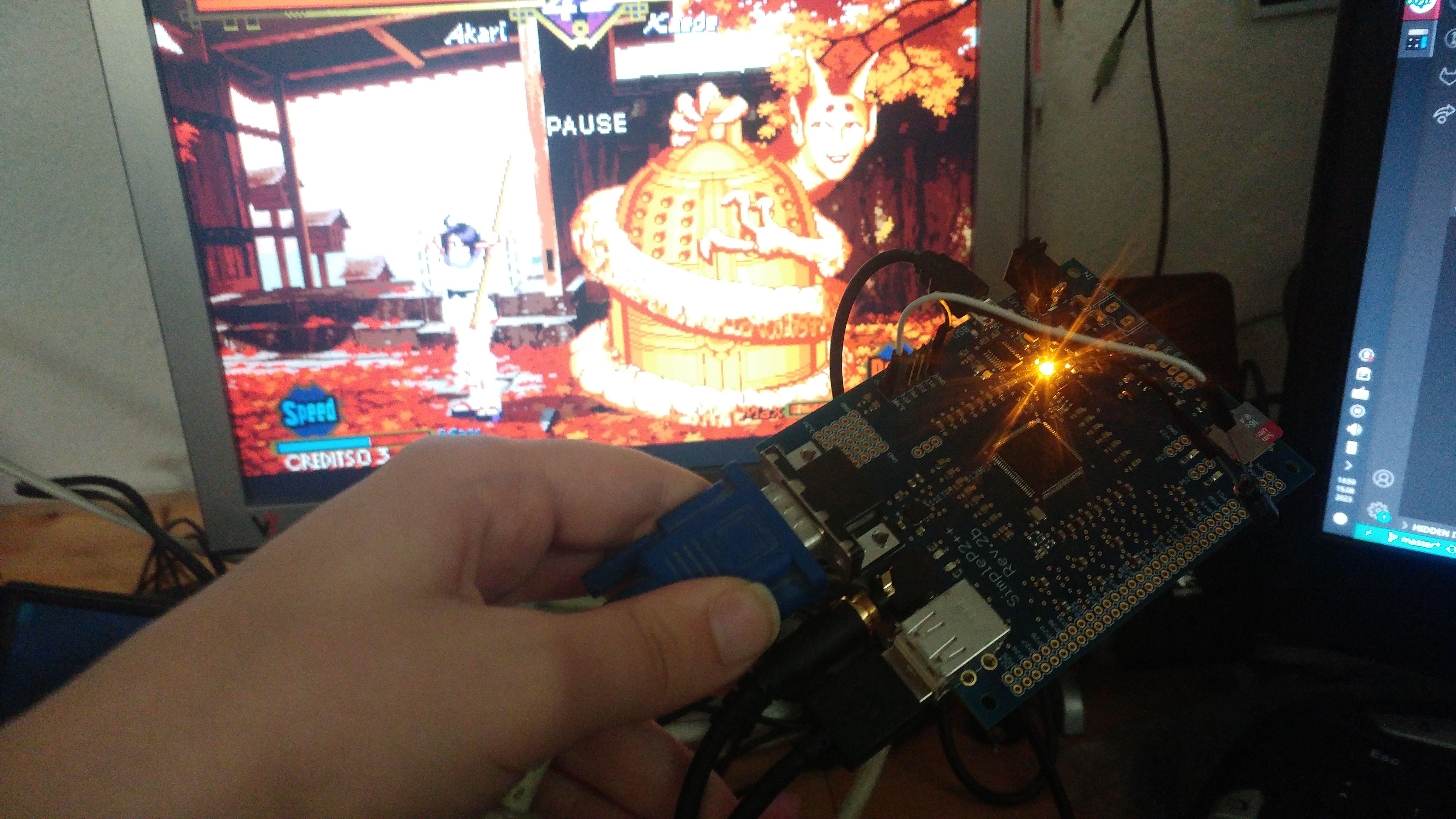
Ray gave me the weird fluke board. It works if I run it at sysclk/3, which is annoying, but hey, it's something.
Power on these needs to be redesigned though. Lots of noise on the audio and card access affects video.
Featuring capacitor bodge that makes the audio slightly better but does nothing else.
I just found the gerbers to examine the layout:
You've got a serious thermal barrier on the bottom layer. The ring of capacitors is cutting off the dissipation path. The Eval and Edge boards certainly solved this with the caps all placed on the top layer instead. I guess that's why the signals all ended up in a middle layer with them. Which should also make the analogue quieter. I'd probably try merge the two existing middle layers - to make room for that middle signal layer.
An alternative might be leave the via grid exposed on the bottom, like the Prop2-Stamp. Allowing for a heatsink attachment.
I don't think thermals are the problem. The Stamp gets really, really hot. Hurts to touch the P2 chip. This doesn't get anywhere near that hot. So the thermals are working good enough I feel. Real issue to focus on is why the RAM is so flaky. (And aforementioned analog A/V interference issues)
The other possibility would be to switch to a different memory that may actually be rated for the speeds we drive it. I think there's a single-chip 3 volt 64MB HyperRAM now (IS66WVH64M8DBLL).
Though idk how the performance would actually compare to sysclk/3 PSRAM. HyperRAM has loooong setups.
That's odd. Why is the paste making a difference? Or are those just coincidences?
Maybe suboptimal power + suboptimal layout + random chip variation wrt to overclockability. Reminder that these all seemingly work at slightly lower sysclock used by megayume.
With this board only the first lane at pin 32 works properly at 338Mhz/2.
The other lanes are instant fails and don't seem to work on any timing setting.
(Note: empirics above may only apply to bank 1 or 2. Forget what I used to test)
That's saying the paste tests are just coincidence.
I would say so. Working sysclk/3 setting means the P2 core isn't having thermal issues. Though the RAMs can have thermal issues, too, I think. My 96MB EVAL setup stopped working reliably after a while of running in the heat outside for a while (a few weeks ago when it was really hot). That affected one bank only I think. Anyways, don't think that's it because it fails immediately on cold boot.
There seem to be two thermal issues. One where NeoYume won't even start. Chip itself is still cold. Another one where NeoYume freezes after several minutes. Was able to fix that with a little fan.
I've made several boards (around 6, I think) with the 5-mil stencil and none of them work for NeoYume, won't even start it.
Guess I can't prove the stencil thickness is the issue yet.
But, I just bought a 7-mil stencil and that will hopefully put this to rest.
@Wuerfel_21 Thanks for telling me about the audio and video noise. As @evanh pointed out, I have place on the bottom of the board for an extra capacitor for every supply pin.
Wasn't planning on populating it, but maybe I should... Guess question is whether to use big C or little C there...
Ideally you'd have a separate VIO rail for the AV section, I think?
Anyways, I don't think the cold issue is infact a thermal issue. Maybe it is power, too? What's the tolerance on those regulators? Maybe it's a supply voltage issue. That would explain why adding the amp chip made the board more flaky. It consumes power and causes the VIO rail to drop. Clocking the RAMs so high might require a voltage more towards the higher end of the allowed range. This is how PC DDR memory achieves its peak perfomance afterall, wherein the motherboard has adjustable regulators to dial in the right voltage as specified by the RAM module's EEPROM. I'll compare the VIO levels on this board with the Edge and Eval. There might be something to that.
Call me crazy but the worst board has the lowest in-game VIO and also the highest difference between menu and in-game...
Caveats:
I don't have a bench power supply (and a precise one at that), but if I did, I would try setting it to 3.4 V (which is in acceptable range for P2 and RAMs) and try to run a board with the instant-crash issue off that. Would need to set DIRECT_BOOT since in absence of the 5V rail we can't control the game menu.
An oscilloscope is needed to check what, in reality, is going on with this VIO voltage. This 0.04 V drop is not relevant, but the meter averages what it gets. There may be short pulses of voltage low or high enough to make things working bad.
Possibly, yes. I'd have hoped for more decisive values. PC RAMs get about 0.1 to 0.2 more than usual when running in "extreme" mode, so that's what I was coming from. As mentioned, the Simple boards were measured with fat capacitor added. I only have an analog scope (whose calibration I don't really trust), so not sure how useful that'll be.
Oh? Oh! Second look and I see now you've duplicated the caps from the top. Oh-oh, and third look you've got pin6, the SCLK pins, of the PSRAMs going to ... pin P30 .... eek! Even using an oscillator module might not be good enough in this setup.
You want to be supporting that V2831 power rail to keep XIN as clean as possible, and ditch the crystal for a module if you haven't already. Better still, move the SCLK well away, say up at pin P48. And may as well move the other three on pins P28..P31 too.
I think I noted that a while back as well...
Also some other information here might be relevant if you don't get a good PSRAM delay test result at the frequency of operation of NeoYume.
https://forums.parallax.com/discussion/comment/1550948/#Comment_1550948
Another idea is if you have a known bad board that fails and some spare PSRAMs, maybe you could solder a new set of them in and see if they help, assuming you are willing to potentially waste these if you can't reuse them later. Better of course to try to first pinpoint which RAMs are slower and failing at high speeds so you just swap those ones out. My delay test can be configured to show the first data error results which may help identity which nibbles are bad. Also do bear in mind this is still overclocking PSRAMs so not all manufactured PSRAMs might be capable of running NeoYume, even though I think most of the parts I've used seem to be capable of high speed operation at this frequency at least with P2-EVAL in my experiments when you don't have the high fanout.
Another possible improvement for new boards that I was just reminded of: Since the SD pins are already non-standard, maybe make the full 4 bit pinout available. @evanh was working on a driver, so I guess he can illuminate us on the ideal pin arrangement.
Roger's pinout is working so far (haven't done any data writes as yet) - https://forums.parallax.com/discussion/174988/new-sd-mode-p2-accessory-board/p1
In the absence of any better pinout the pin mapping I came up with should work okay if you can afford 8 pins for SD. This pinout worked for me at the time I messed with it (no writes there yet either but I don't see an issue with that). It does burn two additional pins over the raw 6 needed for 4 bit SD mode but for that you get card power on/off (which is really needed for full SD card reset reliability) and a card detection feature plus a useful activity LED. Also these extra two pins can potentially do double duty as smartpins that are both within a working distance of the CMD pin. I think Evan may have already made use of that at some point.
I managed to get it to also still support SPI mode, albeit with some flexspin driver tweaks evanh mentioned were needed after some optimization he added. I'd expect supporting SPI mode as well is still probably somewhat important for codebases where you don't have an SD driver. E.g. running something like native micropython for example.
Ha, had to scratch my head on recovering that from dusty memories - Used a serial rx smartpin half way between the CLK and DAT0(MISO) pins to get enough reach out of the +-3 pin input range.
PS: That was only a hack. I never submitted it to Eric.
EDIT: Hmm, on second thoughts, I seem to have made it robust enough. Maybe I could send it Eric's way after all ...
How it is:
    spm_rx = ((PIN_CLK - PIN_DO) & 7) << 24;  // clock pin offset for rx smartpin
    spm_rx |= P_SYNC_RX | P_OE | P_INVERT_OUTPUT | P_HIGH_15K | P_LOW_15K;  // rx smartpin mode, with 15 k pull-up
    _pinstart( PIN_DO, spm_rx, 7 | 32, 0 );  // 8-bit, sample after rising clock + 1 tick delay (smartB registration)
What I changed it to back then:
if( abs(PIN_CLK - PIN_DO) <= 3 ) { spm_rx = ((PIN_CLK - PIN_DO) & 7) << 24; // clock pin offset for smartB input to rx smartpin spm_rx |= P_SYNC_RX | P_OE | P_INVERT_OUTPUT | P_HIGH_15K | P_LOW_15K; // rx smartpin mode, with 15 k pull-up } else { if( PIN_CLK > PIN_DO ) { SMPIN_DO = PIN_CLK - 3; if( (SMPIN_DO == PIN_DI) || (SMPIN_DO == PIN_SS) ) SMPIN_DO++; if( (SMPIN_DO == PIN_DI) || (SMPIN_DO == PIN_SS) ) SMPIN_DO++; } else { SMPIN_DO = PIN_CLK + 3; if( (SMPIN_DO == PIN_DI) || (SMPIN_DO == PIN_SS) ) SMPIN_DO--; if( (SMPIN_DO == PIN_DI) || (SMPIN_DO == PIN_SS) ) SMPIN_DO--; } spm_rx = ((PIN_DO - SMPIN_DO) & 7) << 28; // rx data pin offset for smartA input to rx smartpin spm_rx |= ((PIN_CLK - SMPIN_DO) & 7) << 24; // clock pin offset for smartB input to rx smartpin spm_rx |= P_SYNC_RX; // rx smartpin mode _pin_do = PIN_DO = SMPIN_DO; } _pinstart( PIN_DO, spm_rx, 7 | 32, 0 ); // 8-bit, sample after rising clock + 1 tick delay (smartB registration)Hmm, I just looked at the datasheet and it seems the regulators for the 1v8 and 3v3 rails are only specced for 500mA output current. The Edge module has 3A capacity for 1v8 and 300mA per pingroup (so 2.4A total) for VIO.
I have a program (OPNAcog example) that causes the regulators and associated coils to whine their heart out. It's amplified on the audio out, but I can hear it even just putting my ear near the board.
@Wuerfel_21 Think 500 mA is plenty. It is less than Edge, that's true...
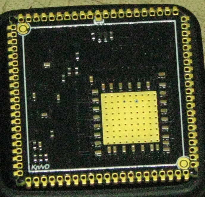
Here's prototype of a version of the board for robots:
So I got out the scope...
VIO on the green board + A/V accessory, running aforementioned OPNAcog VGM plaxer example.
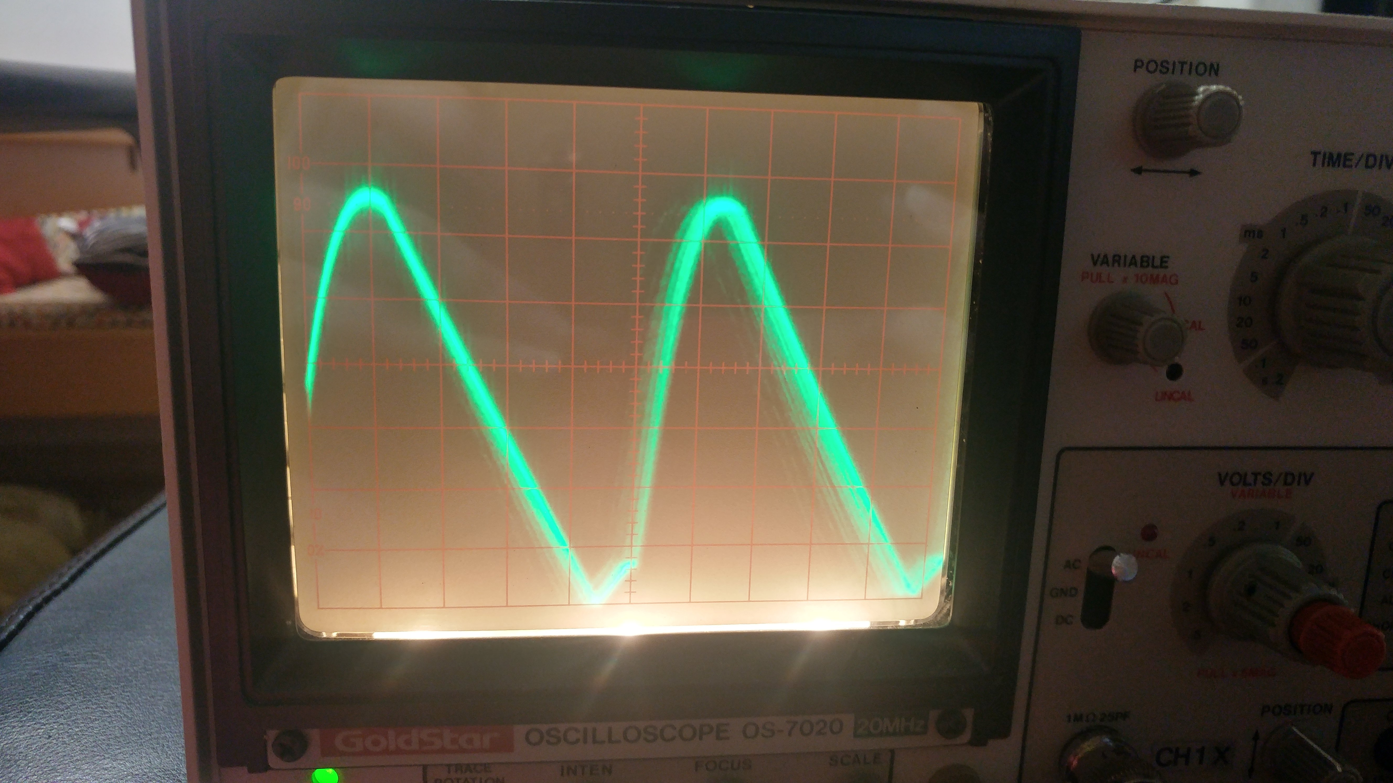
20mV/div 20µs/div
~9kHz tone on the power rail? Cool. (Frequency fluctuates in beat with the music)
meanwhile, VIO on P2EVAL, (notice the scale)
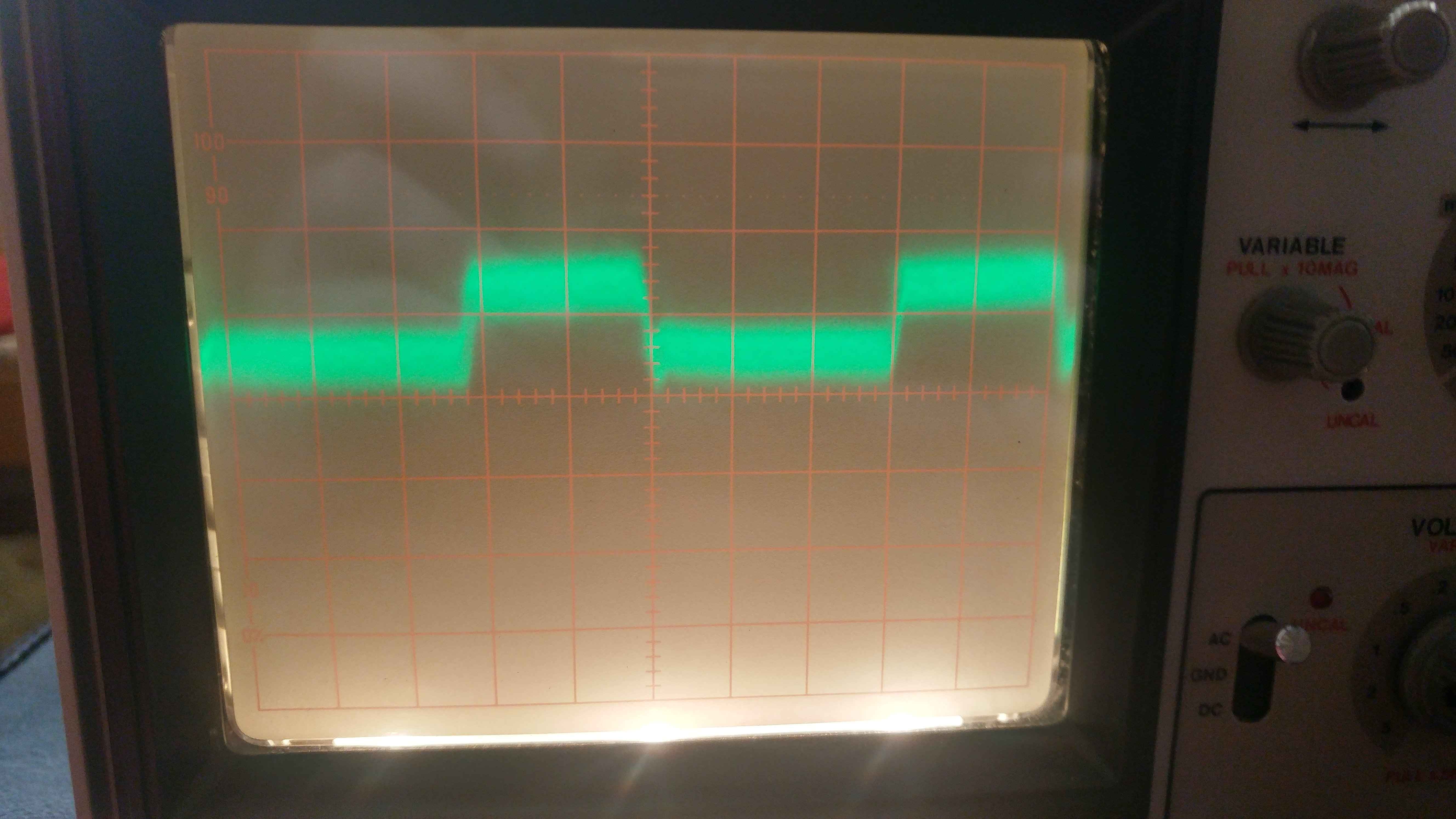
5mV/div 0.2µs/div
Though in my testing with NeoYume, the whine sometimes goes away... Need to see if I can get that on scope. Maybe that's the regulator switching between its PFM and PWM modes? The datasheet alleges that there's a -B version of the device that doesn't have the PFM mode to avoid it's ripply nonsense.
OPNAcog VGM sounds like some kind of torture test?
I'm wondering if 10 uF caps on the bottom of the board will help with the audio situation.
I think that PFM stuff is just for low current mode. I don't think that's relevant in your tests...