@jmg I am not entirely sure U2 is needed. It is for ESD protection. It is used on some of the boards from Wiznet and not on others (see below). I am hoping that the stencil will help place the solder paste only on the pads. I may omit U2 it if it is a PIA.
You really needn't feel guilty about the vias - there's not many by comparison with other boards. If it makes you feel better, many P2 boards (P2 edge, eval included) have 64 vias, one per I/O pin, right under the chip. Makes for a clean looking design.
@ke4pjw said:
@jmg I am not entirely sure U2 is needed. It is for ESD protection. It is used on some of the boards from Wiznet and not on others (see below). I am hoping that the stencil will help place the solder paste only on the pads. I may omit U2 it if it is a PIA.
There look to be plenty of gull wing options, even in easy to manage SOT23-6 - you could allow for 2 footprint options, as there is plenty of room ?
Thanks @Rayman ! Well, I have good news and bad news. Good News: I think the component installation went OK for a first timer. Also, I can communicate with the Wiznet. Bad News: I cannot get ethernet to establish a link. At the moment, I am stumped. I removed the ESD chip to ensure that wasn't the problem. I am going to take a real close look and make sure the W6100 doesn't have any solder bridges on the ethernet side of the chip.
@msrobots If I can figure out what I did wrong on the PHY side, I will put a handful up for sale at https://store.griswoldfx.com/
At this point I think it is a solder bridge, as I have compared the board layout to two different reference schematics. Even if it were an impedance mispatch due to layout, it still should be able to establish link. I will take some time this weekend to figure it out.
Success! (Or as the Klingons like to say, Qupla!)
First thing I checked this evening was to simply reflow all of the solder on the W6100. No dice. Next, I checked to see if the oscillator was running. This was a suggestion in the troubleshooting of a similar TI device. If there were no 25Mhz clock, layer 1 won't negotiate. Turned on the old faithful CT Systems Communications service monitor and I could hear full quieting at 25Mhz when the probe was close to the board. So that wasn't it. I decided to check continuity, starting at the chip, out to the magnetics. Sure enough, R2 was the culprit. It just wasn't soldered well. Reflowed the solder, powered it up and link came right up!
Here it is with the new stylish Full Size P2 Edge breakout board.
@ke4pjw said:
Success! (Or as the Klingons like to say, Qupla!)
... I decided to check continuity, starting at the chip, out to the magnetics. Sure enough, R2 was the culprit. It just wasn't soldered well. Reflowed the solder, powered it up and link came right up!
Well done. Always great to get a DIY board to work from scratch.
Updates: I have purchased a proper reflow oven and paste. Parts for 8 boards are on their way and will be here this weekend. I will test proper function of the SPI interface with @Rayman 's code and FlexProp. If there are no problems with the SPI interface, I will make boards available to order on https://store.griswoldfx.com/
Great news...
BTW I hope that they have updated that reflow oven. I purchased same oven seven years ago, and it needed several mechanical upgrades and another firmware before it was usefull.
Temperature readings were un-accurate, no cold junction compensation. Timing on the curve is realy far off. Earth connection not properly attached to chassis. Tape used on hot areas were flameable and needed to be replaced with capton tape.
But after all these small mods, it worked a lot better.
@MAElektronik It was manufactured in 2022. I will check continuity to the chassis from ground. If that is correct, it may have all of the improvements. I didn't see any "tape" in the tray. Was that internal to the oven?
I ran it through a dry test using "wave 2" yesterday. That is the profile for the solder I am going to use. The cool down period diverged from the curve more than expected. I was thinking that was due to not having any boards in the oven.
It appears I have the newer 2020 version. It has 4 heating elements and doesn't suffer from some of the problems as the older ovens. There was no odor coming from the oven when I ran it through it's paces, so the tape mod may not be necessary. The cold junction compensation seems compelling.
I found good information on the mods and 3rd party firmware.
Nice to hear that the Chinese make an effort to improve their products.
Happy reflowing.
Hope i get time to play with the P2, and buy one of your ethernet boards
I have that same oven. It takes some serious tweaking to make it work right. Dont expect to make a good board your first 5-6 tries. After that, its pretty usable.
Some of the best money I have spent was on “SMD practice boards” from Amazon. They have a counter, decoder, and a bunch of LEDs. Its just a $8 blinky board, but its great for calibrating your oven. Get a few of these, populate them, and let ‘er rip in the oven. Cheap test!
I retired that oven (mostly) and now I use a toaster oven. Really good results once you get the hang of it!
The oven worked just fine. The board needed a little rework due to too much paste, but it came right up. Even has the ESD chip installed. I am very happy with this little oven.
@ke4pjw said:
The oven worked just fine. The board needed a little rework due to too much paste, but it came right up. Even has the ESD chip installed. I am very happy with this little oven.
SWEET! That really is a hole-in-one. Always happy to hear of such success!
As promised, boards are available for sale. 5 can ship today. I have parts available to build 4 more, then I need to order new boards. These are much cleaner than the first ones. These all have the ESD protection IC installed.
Many of yall asked for it, now it is here. SPI support for the W6100 is available in my driver, thanks to @JonnyMac and the "jm_spi.spin2" bitbang driver. It appears to fall over much past 10Mhz, but it works. When I have some time, I will see if I can optimize it. Additionally, I may need to do the PIN output inversion trick to support multiple cogs. (The driver is cogless)
It gets to
Cog0 Initialize Ethernet:$0
Cog0 Chip Identification: $0 $0
Cog0 Chip Version: $0 $0
Cog0 Network Configuration locked.
Cog0 Set MAC address: $0:$8:$dc:$0:$0:$1
Cog0 Network Configuration locked.
Cog0 Network Configuration Unlocked.
Cog0 Set Gateway address: 192.168.0.1
Cog0 Set Subnet: 255.255.255.0
Cog0 Set IP Address: 192.168.0.195
Cog0 Network Configuration locked.
Cog0 Configuring Protocol Mode TCP on Socket 1
and there it sits, not reacting to requests.
So it gets to
W6100.Open(port,PM,socket)
not to
debug("Configuring listener on Socket 1")
lets look further... in W6100drv around line 580
REGBUFFER[0] is $1 (CR_open)
gets to writereg(REG_Sn_CR,socket,1,@REGBUFFER)
hangs in loop behind waiting for REGBUFFER[0] = 0
doing readreg(REG_Sn_CR,socket,1,@REGBUFFER)
but REGBUFFER[0] stays at $F6
Cog0 REGBUFFER[0] = $f6
I tried with and without jumper for SPI and elock := W6100.initSPI()
DHCP did not work either I had to put IP in manually.
Cog0 Start
Cog0 Initialize Ethernet:$0
Cog0 Chip Identification: $0 $0
Cog0 Chip Version: $0 $0
Cog0 First Octect of IP is 0. Using DHCP
Cog0 Configuring Protocol Mode UDP on Socket 0
What to try?
Does it need 5V? not lt. schematic
On thing I would like is pins or at least solder points to access unused pins on the headers
Mike,
Sorry you are having trouble with it. I did test that board before I shipped it. It gets power from the 3.2v V16-23 pin. 5V is not used. Based on the Chip ID and Version, it is not talking to the chip. You should see link when you plug a cable in.
Does it indicate link?
Are you using the default pins? (P16-P32)
You should be able to plug J2 into the end connector on whatever board you have and use SPI mode. That way you don't have to use 16 pins. You will need to use elock := W6100.initSPI() instead of elock := W6100.initParallel() You will also have to remove the jumper for SPI mode.
That should work. I am sorry. I did test each of the boards for at least 24 hours before I shipped them. The problem is isolated to CS, A0, A1, or CLK. The link lights show there is power and that there are no problems on the PHY side. I will ship another one out to you today.
I also found a major bug in DHCP. I was not setting the MAC address before requesting DHCP. It worked correctly with testing on Internet Connection Sharing with my laptop, but failed on a proper DHCP server. There were also some magic numbers and improper locking and unlocking of the network. I will have that all fixed and in the repo shortly.


Comments
@jmg I am not entirely sure U2 is needed. It is for ESD protection. It is used on some of the boards from Wiznet and not on others (see below). I am hoping that the stencil will help place the solder paste only on the pads. I may omit U2 it if it is a PIA.
Looks good Terry
You really needn't feel guilty about the vias - there's not many by comparison with other boards. If it makes you feel better, many P2 boards (P2 edge, eval included) have 64 vias, one per I/O pin, right under the chip. Makes for a clean looking design.
There look to be plenty of gull wing options, even in easy to manage SOT23-6 - you could allow for 2 footprint options, as there is plenty of room ?
Boards are in, and they appear to be the correct dimensions. They fit on the Jonny Mac board, Edge mini, and Rev B Eval board.
If I have time this evening, I will paste, pick, place, and solder.
Good luck! Hopefully all the feedback here helped get it right the first time.
Thanks @Rayman ! Well, I have good news and bad news. Good News: I think the component installation went OK for a first timer. Also, I can communicate with the Wiznet. Bad News: I cannot get ethernet to establish a link. At the moment, I am stumped. I removed the ESD chip to ensure that wasn't the problem. I am going to take a real close look and make sure the W6100 doesn't have any solder bridges on the ethernet side of the chip.
wow.
I love it. Any plans to sell some ready build? I have already problems with normal components...
Mike
@msrobots If I can figure out what I did wrong on the PHY side, I will put a handful up for sale at https://store.griswoldfx.com/
At this point I think it is a solder bridge, as I have compared the board layout to two different reference schematics. Even if it were an impedance mispatch due to layout, it still should be able to establish link. I will take some time this weekend to figure it out.
I do think I see what might be a solder bridge in the photo, but hard to tell...
They are usually relatively easy to remove with solder wick...
Success! (Or as the Klingons like to say, Qupla!)
First thing I checked this evening was to simply reflow all of the solder on the W6100. No dice. Next, I checked to see if the oscillator was running. This was a suggestion in the troubleshooting of a similar TI device. If there were no 25Mhz clock, layer 1 won't negotiate. Turned on the old faithful CT Systems Communications service monitor and I could hear full quieting at 25Mhz when the probe was close to the board. So that wasn't it. I decided to check continuity, starting at the chip, out to the magnetics. Sure enough, R2 was the culprit. It just wasn't soldered well. Reflowed the solder, powered it up and link came right up!
Here it is with the new stylish Full Size P2 Edge breakout board.
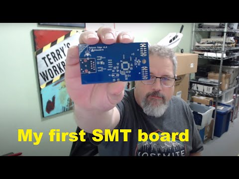
I uploaded a video of assembling this board.
Well done. Always great to get a DIY board to work from scratch.
Great news, Terry. Thanks for sharing so much of the journey, really good to see
Updates: I have purchased a proper reflow oven and paste. Parts for 8 boards are on their way and will be here this weekend. I will test proper function of the SPI interface with @Rayman 's code and FlexProp. If there are no problems with the SPI interface, I will make boards available to order on https://store.griswoldfx.com/
Great news...
BTW I hope that they have updated that reflow oven. I purchased same oven seven years ago, and it needed several mechanical upgrades and another firmware before it was usefull.
Temperature readings were un-accurate, no cold junction compensation. Timing on the curve is realy far off. Earth connection not properly attached to chassis. Tape used on hot areas were flameable and needed to be replaced with capton tape.
But after all these small mods, it worked a lot better.
@MAElektronik It was manufactured in 2022. I will check continuity to the chassis from ground. If that is correct, it may have all of the improvements. I didn't see any "tape" in the tray. Was that internal to the oven?
I ran it through a dry test using "wave 2" yesterday. That is the profile for the solder I am going to use. The cool down period diverged from the curve more than expected. I was thinking that was due to not having any boards in the oven.
Thanks for the heads up!
It appears I have the newer 2020 version. It has 4 heating elements and doesn't suffer from some of the problems as the older ovens. There was no odor coming from the oven when I ran it through it's paces, so the tape mod may not be necessary. The cold junction compensation seems compelling.
I found good information on the mods and 3rd party firmware.
https://hackaday.io/project/175048-t-962a-reflow-oven-modifications/details
Nice to hear that the Chinese make an effort to improve their products.
Happy reflowing.
Hope i get time to play with the P2, and buy one of your ethernet boards
I have that same oven. It takes some serious tweaking to make it work right. Dont expect to make a good board your first 5-6 tries. After that, its pretty usable.
Some of the best money I have spent was on “SMD practice boards” from Amazon. They have a counter, decoder, and a bunch of LEDs. Its just a $8 blinky board, but its great for calibrating your oven. Get a few of these, populate them, and let ‘er rip in the oven. Cheap test!
I retired that oven (mostly) and now I use a toaster oven. Really good results once you get the hang of it!
The oven worked just fine. The board needed a little rework due to too much paste, but it came right up. Even has the ESD chip installed. I am very happy with this little oven.
Very nice. Golfers might call that a hole in one!
Which paste did you use?
I used Sn63/Pb37 from Chip Quick. Seemed to have good reviews.
https://www.amazon.com/dp/B07BH5LP5G?psc=1&ref=ppx_yo2ov_dt_b_product_details
I tell you, I would rather be lucky than good any day of the week") I think the Luck of the Irish was with me on this St Patty's day.
I think the Luck of the Irish was with me on this St Patty's day.
I built and tested 5 this evening. I need to build some written docs for them and will have some up on the website Sunday.
SWEET! That really is a hole-in-one. Always happy to hear of such success!
As promised, boards are available for sale. 5 can ship today. I have parts available to build 4 more, then I need to order new boards. These are much cleaner than the first ones. These all have the ESD protection IC installed.
https://store.griswoldfx.com/spinner-edge/
I have completed the demo code and produced an Operations Manual.
Those that purchased boards, they will ship tomorrow morning.
All links can be found here.
Many of yall asked for it, now it is here. SPI support for the W6100 is available in my driver, thanks to @JonnyMac and the "jm_spi.spin2" bitbang driver. It appears to fall over much past 10Mhz, but it works. When I have some time, I will see if I can optimize it. Additionally, I may need to do the PIN output inversion trick to support multiple cogs. (The driver is cogless)
https://griswoldfx.visualstudio.com/Spinner Edge/_git/Software?path=/&version=GBmain
well my board arrived, but no cigar.
It gets to
Cog0 Initialize Ethernet:$0
Cog0 Chip Identification: $0 $0
Cog0 Chip Version: $0 $0
Cog0 Network Configuration locked.
Cog0 Set MAC address: $0:$8:$dc:$0:$0:$1
Cog0 Network Configuration locked.
Cog0 Network Configuration Unlocked.
Cog0 Set Gateway address: 192.168.0.1
Cog0 Set Subnet: 255.255.255.0
Cog0 Set IP Address: 192.168.0.195
Cog0 Network Configuration locked.
Cog0 Configuring Protocol Mode TCP on Socket 1
and there it sits, not reacting to requests.
So it gets to
W6100.Open(port,PM,socket)
not to
debug("Configuring listener on Socket 1")
lets look further... in W6100drv around line 580
REGBUFFER[0] is $1 (CR_open)
gets to writereg(REG_Sn_CR,socket,1,@REGBUFFER)
hangs in loop behind waiting for REGBUFFER[0] = 0
doing readreg(REG_Sn_CR,socket,1,@REGBUFFER)
but REGBUFFER[0] stays at $F6
Cog0 REGBUFFER[0] = $f6
I tried with and without jumper for SPI and elock := W6100.initSPI()
DHCP did not work either I had to put IP in manually.
Cog0 Start
Cog0 Initialize Ethernet:$0
Cog0 Chip Identification: $0 $0
Cog0 Chip Version: $0 $0
Cog0 First Octect of IP is 0. Using DHCP
Cog0 Configuring Protocol Mode UDP on Socket 0
What to try?
Does it need 5V? not lt. schematic
On thing I would like is pins or at least solder points to access unused pins on the headers
Mike
Mike,
Sorry you are having trouble with it. I did test that board before I shipped it. It gets power from the 3.2v V16-23 pin. 5V is not used. Based on the Chip ID and Version, it is not talking to the chip. You should see link when you plug a cable in.
Does it indicate link?
Are you using the default pins? (P16-P32)
You should be able to plug J2 into the end connector on whatever board you have and use SPI mode. That way you don't have to use 16 pins. You will need to use elock := W6100.initSPI() instead of elock := W6100.initParallel() You will also have to remove the jumper for SPI mode.
I can meetup on Discord to help troubleshoot.
--Terry
I am using pin 16-32 on a jonnyMac Board
Ethernet Cable OK, can run Spinnerette from it.
Tried both,
elock := W6100.initSPI() with jumper removed
elock := W6100.initParallel() with jumper on
Both yellow and green LEDs are on. Yellow sometimes blinking.
will download again, Any other driver to download for test?
helpless
Mike
That should work. I am sorry. I did test each of the boards for at least 24 hours before I shipped them. The problem is isolated to CS, A0, A1, or CLK. The link lights show there is power and that there are no problems on the PHY side. I will ship another one out to you today.
I also found a major bug in DHCP. I was not setting the MAC address before requesting DHCP. It worked correctly with testing on Internet Connection Sharing with my laptop, but failed on a proper DHCP server. There were also some magic numbers and improper locking and unlocking of the network. I will have that all fixed and in the repo shortly.
Regards,
Terry