Building a remote battery powered environment senor
 iseries
Posts: 1,526
For this project I am using the following items:
P2 Edge
Blues Wirless Notecard
Parallax BME680 Sensor
Adafruit INA260 Power Sensor
In building this project I was thinking I was going to have to use a P1 which I thought would use a lot less power than the P2.
The P1 uses about 13ma of power running and 7.5ma when in low power mode.
The P2 on the other hand uses 76ma of power running and 2.7ma when in low power mode.
Using 18650 batteries that are 2000mah in size and doing some rough math:
2000/76 = 26 minutes of run time where as 2000/2.7 = 740 minutes of run time.
Now I won't be using all of the power because the regulator I'm using only work down to 7.2 volts. This shortens the battery life.
I was trying to build a MOSFET switch that would allow the P2 to turn itself off when the battery voltage got down to 7.2 volts. This proved challenging in that I only had P channel FET and running it off the ground side caused some issues with powering it on and it also not a very good one in that the on resistance was a little high. I will have to revisit this with some updated parts.
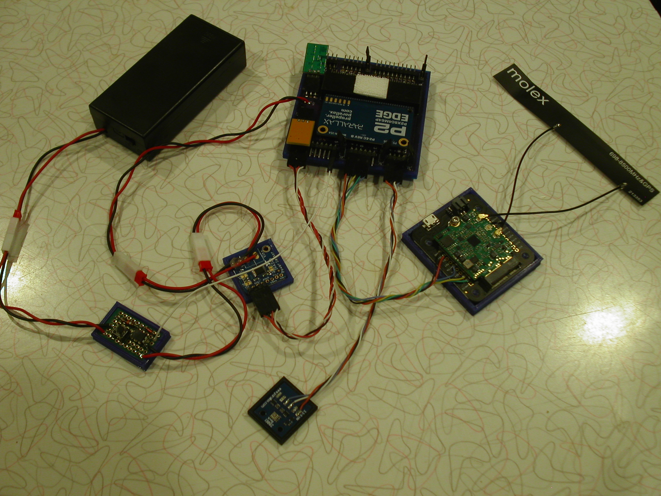
This is what the project looks like:
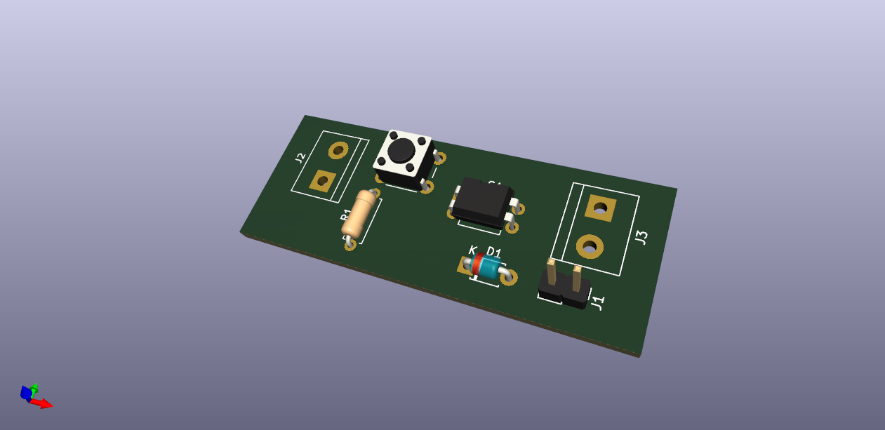
You can see the power switch in the lower left corner which is connect to pin 15 on the P2. The first thing the code does is sets this pin high so the power stays on to the P2. The push button on the power switch is used to power on the P2 until the P2 takes over.
The way this project is going to work is that it will take some readings and then send them to the Notecard that will use a cellular connection and upload the values to their website.
The card is built such that it will only turn on when it needs to send something and then goes into low power mode.
Data to the Notecard is in JSON format so I needed to create a JSON packet with the values and then give it to the Notecard to send:
{
  "current":2,
  "humidity":46.62,
  "pressure":29.39,
  "temperature":21.21,
  "voltage":7335
}
I only want to send data every hour so I need to put the P2 into low power mode for that time period and then wake up to gather the data.
I had some trouble putting the P2 into low power mode and then bringing it back to life. I had to figure out how to use the clkset function and what mode value to use.
void Sleep(int t)
{
    int i;

    i = _clkfreq;
   //Slow speed low power mode
    _clkset(_clkmode ^2, 20000);

    sleep(t);

    _clkset(_clkmode ^2, i);
}
This turned out to be very simple code after all. I didn't want to run the P2 in low power mode because it would mess with the timing and serial data that I needed to send. I did end up running the P2 at 20Mhz instead of 200Mhz to save even more power while it was working on the data.
Here is the finished code:
#include <stdio.h>
#include <propeller.h>
#include "i2c.h"
#include "ina260.h"
#include "bme68x.h"
#include "blueio.h"
#include "json.h"

#define INACLK 8
#define INADTA 9
#define BLURX 20
#define BLUTX 21
#define BLUAT 22
#define BMECLK 36
#define BMEDTA 37
#define PWRPN 15


void StartMonitor(void);
void StartBlue(void);
void StartBME(void);
int GetEnvironment(float *, float *, float *);
void Sleep(int);


char Buffer[1024];
char Convert[25];
char fmt[] = "%4.2f";
i2c_t *Bme;
char dev_addr;
struct bme68x_dev gas_sensor;
struct bme68x_conf conf;
struct bme68x_heatr_conf heatr_conf;
struct bme68x_data data[3];


int main(int argc, char** argv)
{
    float t, h, p;
    int v, c;

    _pinl(56);
    _pinl(57);

    /* Enable Power Switch */
    _pinh(PWRPN);

    /* 20Mhz for lower power use */
    _clkset(0x010000fb, 20000000);

    StartMonitor();
    StartBME();
    StartBlue();

    _pinl(56);
    _pinl(57);

    while (1)
    {
        GetEnvironment(&t, &h, &p);
        v = INA260_getVoltage();
        c = INA260_getCurrent();
        json_init(Buffer);
        sprintf(Convert, fmt, t);
        json_putDec("temperature", Convert);
        sprintf(Convert, fmt, h);
        json_putDec("humidity", Convert);
        sprintf(Convert, fmt, p);
        json_putDec("pressure", Convert);
        sprintf(Convert, "%d", v);
        json_putDec("voltage", Convert);
        sprintf(Convert, "%d", c);
        json_putDec("current", Convert);
        Blueio_Add(Buffer);
        Blueio_Sync();
        //printf("temp: %3.2f, humidity: %3.2f, pressure: %3.2f, voltage: %d, current: %d\n", t, h, p, v, c);
        _waitms(10000);

        /* Low Battery Cutoff */
        if (v < 7200)
            _pinl(PWRPN);
        Sleep(3600);
    }
}

void StartMonitor()
{
    int i;

    i = INA260_open(INACLK, INADTA);
    if (i =! 0x5449)
    {
        _pinh(57);
        while (1)
            Sleep(60);
    }

    INA260_configAveraging(7);
    INA260_configCurrent(7);
    INA260_configVoltage(7);
}

void StartBlue()
{
    int i;

    i = Blueio_Init(BLURX, BLUTX);
    if (i != 352)
    {
        _pinh(56);
        _pinh(57);
        while (1)
            _waitms(500);
    }
}

void StartBME()
{
    int rslt;
    float t, h, p;

    Bme = I2C_Init(BMECLK, BMEDTA, I2C_STD);

    dev_addr = BME68X_I2C_ADDR_HIGH;
    gas_sensor.variant_id = BME68X_VARIANT_GAS_LOW;
    gas_sensor.intf = BME68X_I2C_INTF;
    gas_sensor.read = BME68xRead;
    gas_sensor.write = BME68xWrite;
    gas_sensor.delay_us = BME68xWait;
    gas_sensor.amb_temp = 25;
    gas_sensor.intf_ptr = &dev_addr;
    rslt = bme68x_init(&gas_sensor);
    if (rslt != BME68X_OK)
    {
        _pinh(56);
        while (1)
            Sleep(60);
    }

    /* Set the temperature, pressure and humidity settings */
    conf.os_hum = BME68X_OS_16X;
    conf.os_pres = BME68X_OS_1X;
    conf.os_temp = BME68X_OS_2X;
    conf.filter = BME68X_FILTER_OFF;
    conf.odr = BME68X_ODR_NONE;
    rslt = bme68x_set_conf(&conf, &gas_sensor);
    if (rslt != BME68X_OK)
    {
        _pinh(56);
        while (1)
            Sleep(60);
    }

    /* Set the remaining gas sensor settings and link the heating profile */
    heatr_conf.enable = BME68X_ENABLE;

    /* Create a ramp heat waveform in 3 steps */
    heatr_conf.heatr_temp = 300; /* degree Celsius */
    heatr_conf.heatr_dur = 100; /* milliseconds */
    heatr_conf.heatr_temp_prof = NULL;
    heatr_conf.heatr_dur_prof = NULL;
    heatr_conf.profile_len = 0;

    rslt = bme68x_set_heatr_conf(BME68X_FORCED_MODE, &heatr_conf, &gas_sensor);

    /* kick off a reading */
    GetEnvironment(&t, &h, &p);
}

int GetEnvironment(float *temp, float *humidity, float *pressure)
{
    int rslt;
    int delay;
    int f;

    rslt = bme68x_set_op_mode(BME68X_FORCED_MODE, &gas_sensor);
    delay = bme68x_get_meas_dur(BME68X_FORCED_MODE, &conf, &gas_sensor) + (heatr_conf.heatr_dur * 1000);
    gas_sensor.delay_us(delay, gas_sensor.intf_ptr);
    rslt = bme68x_get_data(BME68X_FORCED_MODE, &data, &f, &gas_sensor);
    *temp = data[0].temperature;
    *humidity = data[0].humidity;
    *pressure = data[0].pressure/3386.4;
}

uint8_t BME68xRead(uint8_t reg_addr, uint8_t *data, uint16_t len, void *intf_ptr)
{
    int i;

    uint8_t dev_addr = *(uint8_t*)intf_ptr;

    i = I2C_In(Bme, dev_addr, reg_addr, 1, data, len);

    if (i > 0)
        return 0;
    else
        return -1;
}

uint8_t BME68xWrite(uint8_t reg_addr, uint8_t *data, uint16_t len, void *intf_ptr)
{
    int i;

    uint8_t dev_addr = *(uint8_t*)intf_ptr;

    i = I2C_Out(Bme, dev_addr, reg_addr, 1, data, len);

    if (i > 0)
        return 0;
    else
        return -1;
}

void BME68xWait(uint32_t period, void *intf_ptr)
{
    _waitus(period);
}

void Sleep(int t)
{
    int i;

    i = _clkfreq;
   //Slow speed low power mode
    _clkset(_clkmode ^2, 20000);

    sleep(t);

    _clkset(_clkmode ^2, i);
}
Next, I need to build a web service and have the Notecard send the data to my web service instead of just putting it on their site.
Mike


Comments
Both Prop1 and Prop2 can run on lower supply voltages. 3.3 Volts is only needed for max speed. So a single cell battery with a 3.0V LDO regulator will work fine. Even lower if you really want.
Prop1 at RCSLOW is only a few microamps. Twenty tops with all eights cogs running spin at 3.3 Volts.
@evanh ,
I tested both a Flip and a Propeller Mini and both had higher readings then the P2 probably because of the LDO's on the boards.
This was with RCSLOW enabled.
Using higher battery to drive Notecard that can use a lot of power when it needs to send data.
Mike
Oh, yeah, I guess the LDO is hungry. Well, a single cell battery with just a diode drop or two might be suitable voltage.
What voltage range can that run on?
@evanh,
The unit was designed to run off a small single cell lipo battery so 3 to 4 volts up to 5.5 volts.
Mike
Found some DC-DC converters with impressive low power specs - https://www.ti.com/product/TPS82740B/part-details/TPS82740BSIPR
Have to say the naming is a tad dopey though. A grid of contacts is anything but a Single Inline Package.
I have been running the environment sensor for a couple of days now and the battery voltage is holding.
I should be able to power it for about 2 weeks on charge.
The voltage on the battery has dropped about 43mv in 24 hours.
So going from 7788 to 7200 millivolts or 588 mv drop divided by 43mv per day equals: 13 days.
Now that assumes the battery voltage is linear which might not be the case.
What would be the rating on these 18650 batteries that I harvested from an old laptop computer?
8200mv - 6000mv = 2200mv
2200mv / 43mv = 51 days
51days * 24 hours = 1224 hours
1224 hours * 2ma = 2448 mah battery.
That seems about right but I think as the battery voltage drops the current is going to go up to maintain the same amount of power used by the environment and the battery voltage is not linear.
Mike
You might want to use more than one battery cell in parallel for running time if you are looking for something that is 2 battery cells in series this might be what you are looking for
https://batteryhookup.com/products/new-7-2v-30ah
I have bought about 10 of these packs and they do test at 26 amp hours at one amp load from 8.40 volts fully charged and discharged to 6.00 volts the roll of voltage is about 6.30 so your useable voltage range is 8.4 volts to 6.30 volts
I am making a battery pack for my battery operated air compressor for remote use when power is not available I still have to wire the battery cells together and install the BMS protection boards
One note make sure that you use some type of BMS protection board even if it from a USB battery bank power supply which works very well I have use them in the past one thing that is nice about them you have a fuel gauge that comes in very handy for checking the battery voltage
Most of the time I remove the battery cells from them and put brand name battery cells
and remove the non brand name battery cells
Use them in something that does not need very much current or something that is not very important if runs down to soon
I hope this helps you
I'm a little confused as to the limit of 5.5 Volts being exceeded.
The 5.5 volts is the maximum for the ic chip that you posted what you could do is just split into two parallel cell packs tied together / instead series/ parallel which is way it comes the battery pack that I referred to earlier in the above post and instead of 26 amp hours you could 52 amp hours
Oh, so the 8 Volt calculations are not the actual wired voltage?
It's been over a week now and the battery pack is doing just fine. I did however discover that the website only keeps about one weeks worth of data so I need to pull my numbers and save them somewhere.

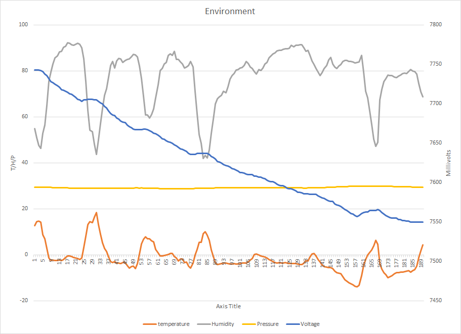
I can see from the chart that when the temperature goes down the voltage also goes down and when the temperature rises so does the voltage.
I also realized that I can dump the 5 volt regulator on the front side because I'm using a Rev C P2 that doesn't require 5 volts input. This means I could run the batteries down to 6 volts instead of the 7.2 for my regulator.
8v - 6v = 2v / 30ma = 66.6 days of operation on two 18650 batteries in series.
Mike
Yes you can however you will run into a problem with stability when you get to about 3.60 or so because your battery voltage will be come unstable because at this point your battery pack will be out of power and your buck converter will cycle out and when the battery cell voltage comes back up a little bit your converter will probably power on again
One solution would be to not run the battery pack down to anything below 7.0 volt or find a BMS board that once the battery voltage goes below the cutoff voltage it stays locked out until you the charger voltage to it to reset the BMS protection board
There are some very good usb battery backup packs out there that would work perfectly for what you are wanting to do you can even buy them from Walmart or Target or Best Buy
The issue you might have with the very inexpensive ones is that the battery cells are made in China and there quality is hit and miss type thing
Now if you want to run it off of 5 volts and use a 3.3 volts then you could do this
So if you buy a inexpensive usb battery pack that has a plastic enclosure and carefully open it and replace the battery cells with a brand name battery cells the performance of them will greatly improved
Everything was going fine till the other day. All of a sudden, I saw two hourly events didn't show up in the cloud.
The last event showed the battery was at 7.5 volts so the power to the unit should be good.
I panicked and retrieved the unit to check it out. I had the unit in a box so I could just bring it in and take a look.
Everything looked fine so I didn't know if the software went south and locked up since I had no LED's on or flashing pulses to see if it was alive.
I got my meter out and check the battery voltage and the regulators output voltage and all was good.
I decided to just leave it and see what happens.
Low and be hold the data showed up the next day when I checked the cloud. When I see the entries in the cloud I see my environment data and then a sync request right after that saying was asked to sync which the program does. I guess you could give the unit a couple of pieces of data and then tell it send it.
When I look at the cloud data I see three data packets and then the sync request. Each packet is time stamped with when it was sent to the Notecard and another with when it was uploaded to the cloud. It showed that the data was given to the Notecard on time but failed to send it to the cloud.
Did I have a cellular failure or some other issue? I guess I might need to add an SD card to my project and log all the JSON data moving about.
Well after that there was another missed upload event and this time the unit was still sitting on my desk so it should have had good cell reception.
There was only two of these events and they both happened next to each other and that was it. The data after that was normal so maybe there was an issue with their cloud servers?
Anyway, no data was lost! The Notecard did its job and made sure the data made it to the cloud just maybe not on time.
So far so good.
Mike
There is now three certainties in life: Death, taxes and an inconsistent Internet. Hell, it was built from the start with the assumption of expecting variable service.
If I read the specs right, seems there's a bit of a local buffer: 2MB of flash and 640KB of RAM
(if indeed that was the issue, rather than cloud backlog as you pondered)
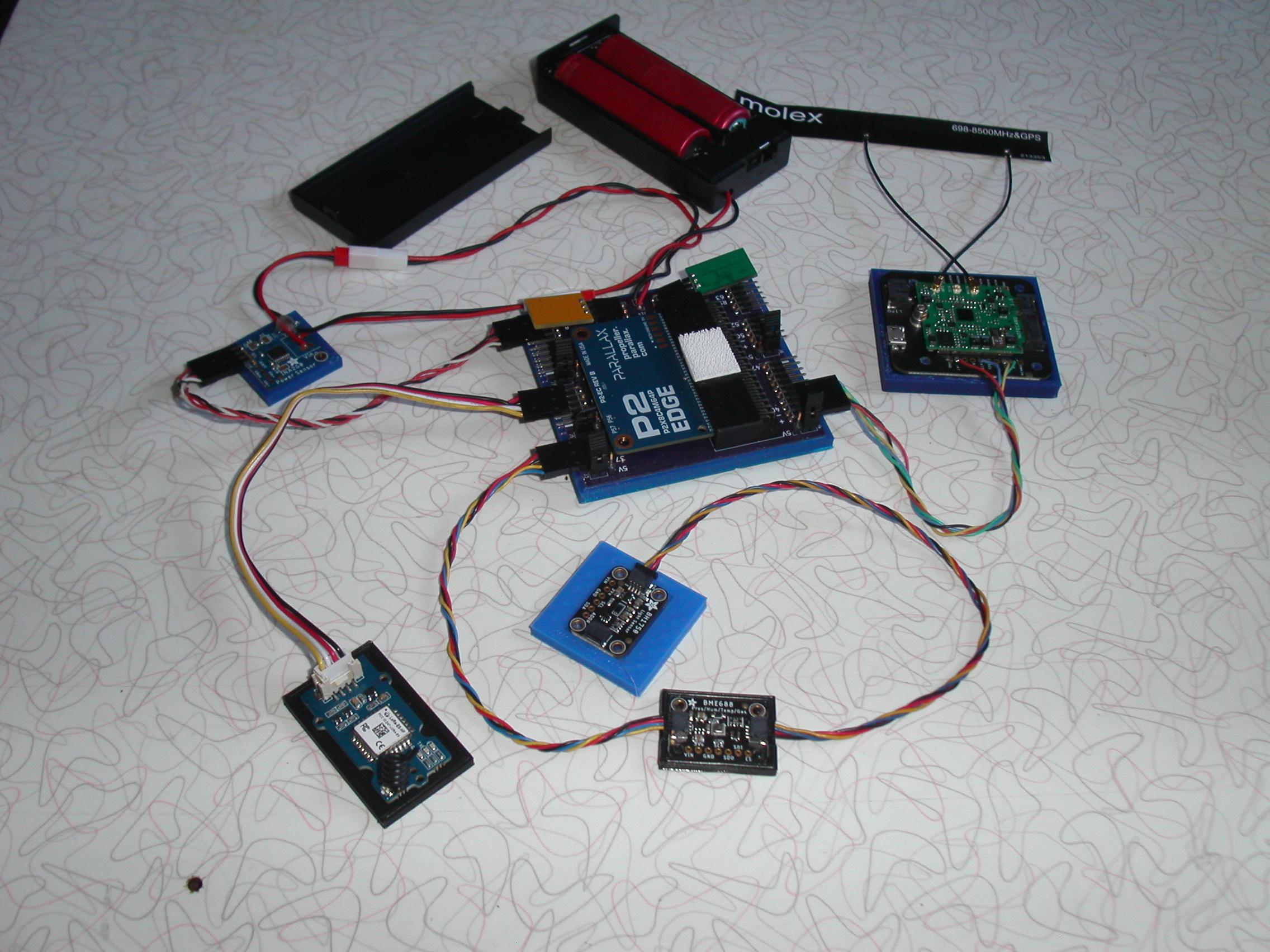
I decided to upgrade my configuration a little.
I was running two P2's one with Notecard and one with LoraWan. Since I'm short on P2's I decided to join the two and save a P2.

Since everything is plug and play it was a simple matter of moving the LoraWan over to the Notecard unit and moving the Notecard to a different port.
I also decided to add a light sensor to the configuration while I was at it. While I could have used a new port on the P2 I decided to use the QWIIC daisy chain instead since they are just I2C devices. I also dropped the real time clock in favor of the clock on the Notecard.
Now all the data is sent by two ways. The Notecard and the LoraWan unit. All the data ends up in the cloud where I use a .Net appliance to read the data once a day and place it in a file for review.
My current draw has increased a little to about 8ma, so I don't know what device is using more power. I may have to look into that.
Mike
#include <stdio.h>
#include <propeller.h>
#include "i2c.h"
#include "ina260.h"
#include "bme68x.h"
#include "blueio.h"
#include "json.h"
#include "wioe5.h"
#include "bh1750.h"


#define INACLK 8
#define INADTA 9
#define BLURX 40
#define BLUTX 41
#define BLUAT 42
#define LRTX 20
#define LRRX 21
#define BMECLK 36
#define BMEDTA 37
#define PWRPN 15

void StartLight(void);
void StartMonitor(void);
void StartBlue(void);
void StartLora(void);
void SendLora(char*);
void StartBME(void);
int GetEnvironment(float *, float *, float *);
void Sleep(int);
void Hex(void *);


char Buffer[1024];
char Convert[64];
char fmt[] = "%4.2f";
i2c_t *Bme;
time_t tm;
char dev_addr;
struct bme68x_dev gas_sensor;
struct bme68x_conf conf;
struct bme68x_heatr_conf heatr_conf;
struct bme68x_data data[3];


int main(int argc, char** argv)
{
    float t, h, p;
    int v, c, l;

    _pinl(56);
    _pinl(57);

    /* 20Mhz for lower power use */
    _clkset(0x010000fb, 20000000);

    StartLight();
    StartMonitor();
    StartBME();
    StartLora();
    StartBlue();

    while (1)
    {
        GetEnvironment(&t, &h, &p);
        v = INA260_getVoltage();
        c = INA260_getCurrent();
        l = BH1750_Read();
        tm = Blueio_GetTime()-18000;
        Buffer[0] = 0;
        Hex(&t);
        Hex(&h);
        Hex(&p);
        Hex(&v);
        Hex(&c);
        Hex(&l);
        Hex(&tm);
        //WIOE5_SendLora(Buffer);
        WIOE5_SendConfirmedHex(Buffer);
        json_init(Buffer);
        sprintf(Convert, fmt, t);
        json_putDec("temperature", Convert);
        sprintf(Convert, fmt, h);
        json_putDec("humidity", Convert);
        sprintf(Convert, fmt, p);
        json_putDec("pressure", Convert);
        sprintf(Convert, "%d", v);
        json_putDec("voltage", Convert);
        sprintf(Convert, "%d", c);
        json_putDec("current", Convert);
        sprintf(Convert, "%d", l);
        json_putDec("light", Convert);
        Blueio_Add(Buffer);
        Blueio_Sync();
        //printf("Date: %s", asctime(localtime(&tm)));
        //printf("temp: %3.2f, humidity: %3.2f, pressure: %3.2f, voltage: %d, current: %d, light: %d\n", t, h, p, v, c, l);
        _waitms(10000);

        WIOE5_SetLowPower(0);

        Sleep(3600);

        WIOE5_SetLowPower(3);
    }
}

void StartLight()
{
    int i;

    i = BH1750_Init(BMECLK, BMEDTA);

    BH1750_Cmd(BH1750_PWR_UP);

    BH1750_Cmd(BH1750_CHRM);
}

void StartMonitor()
{
    int i;

    i = INA260_open(INACLK, INADTA);
    if (i =! 0x5449)
    {
        _pinh(57);
        while (1)
            Sleep(60);
    }

    INA260_configAveraging(7);
    INA260_configCurrent(7);
    INA260_configVoltage(7);
}

void StartBlue()
{
    int i;

    i = Blueio_Init(BLURX, BLUTX);
    if (i != 352)
    {
        _pinh(56);
        _pinh(57);
        while (1)
            _waitms(500);
    }

    /* status of the Notecard */
    for (int j=0;j<120;j++)
    {
        i = Blueio_Status();
        if (i > 0)
            break;
        _waitms(1000);
    }

}

void StartLora()
{
    int i;

    i = WIOE5_Init(LRRX, LRTX);
    if (i != 4011)
    {
        _pinh(56);
        _pinh(57);
        printf("ver: %d\n", i);
        while (1)
            _waitms(500);
    }

    // Set Point to Point Config
    // WIOE5_SetLora(0);
    // Set Join Network
    WIOE5_Join();
}

void StartBME()
{
    int rslt;
    float t, h, p;

    Bme = I2C_Init(BMECLK, BMEDTA, I2C_STD);

    dev_addr = BME68X_I2C_ADDR_HIGH;
    gas_sensor.variant_id = BME68X_VARIANT_GAS_LOW;
    gas_sensor.intf = BME68X_I2C_INTF;
    gas_sensor.read = BME68xRead;
    gas_sensor.write = BME68xWrite;
    gas_sensor.delay_us = BME68xWait;
    gas_sensor.amb_temp = 25;
    gas_sensor.intf_ptr = &dev_addr;
    rslt = bme68x_init(&gas_sensor);
    if (rslt != BME68X_OK)
    {
        _pinh(56);
        while (1)
            Sleep(60);
    }

    /* Set the temperature, pressure and humidity settings */
    conf.os_hum = BME68X_OS_16X;
    conf.os_pres = BME68X_OS_1X;
    conf.os_temp = BME68X_OS_2X;
    conf.filter = BME68X_FILTER_OFF;
    conf.odr = BME68X_ODR_NONE;
    rslt = bme68x_set_conf(&conf, &gas_sensor);
    if (rslt != BME68X_OK)
    {
        _pinh(56);
        while (1)
            Sleep(60);
    }

    /* Set the remaining gas sensor settings and link the heating profile */
    heatr_conf.enable = BME68X_ENABLE;

    /* Create a ramp heat waveform in 3 steps */
    heatr_conf.heatr_temp = 300; /* degree Celsius */
    heatr_conf.heatr_dur = 100; /* milliseconds */
    heatr_conf.heatr_temp_prof = NULL;
    heatr_conf.heatr_dur_prof = NULL;
    heatr_conf.profile_len = 0;

    rslt = bme68x_set_heatr_conf(BME68X_FORCED_MODE, &heatr_conf, &gas_sensor);

    /* kick off a reading */
    GetEnvironment(&t, &h, &p);
}

int GetEnvironment(float *temp, float *humidity, float *pressure)
{
    int rslt;
    int delay;
    int f;

    rslt = bme68x_set_op_mode(BME68X_FORCED_MODE, &gas_sensor);
    delay = bme68x_get_meas_dur(BME68X_FORCED_MODE, &conf, &gas_sensor) + (heatr_conf.heatr_dur * 1000);
    gas_sensor.delay_us(delay, gas_sensor.intf_ptr);
    rslt = bme68x_get_data(BME68X_FORCED_MODE, &data, &f, &gas_sensor);
    *temp = data[0].temperature;
    *humidity = data[0].humidity;
    *pressure = data[0].pressure/3386.4;
}

uint8_t BME68xRead(uint8_t reg_addr, uint8_t *data, uint16_t len, void *intf_ptr)
{
    int i;

    uint8_t dev_addr = *(uint8_t*)intf_ptr;

    i = I2C_In(Bme, dev_addr, reg_addr, 1, data, len);

    if (i > 0)
        return 0;
    else
        return -1;
}

uint8_t BME68xWrite(uint8_t reg_addr, uint8_t *data, uint16_t len, void *intf_ptr)
{
    int i;

    uint8_t dev_addr = *(uint8_t*)intf_ptr;

    i = I2C_Out(Bme, dev_addr, reg_addr, 1, data, len);

    if (i > 0)
        return 0;
    else
        return -1;
}

void BME68xWait(uint32_t period, void *intf_ptr)
{
    _waitus(period);
}

void Sleep(int t)
{
    int i;

    i = _clkfreq;
   //Slow speed low power mode
    _clkset(_clkmode ^2, 20000);

    sleep(t);

    _clkset(_clkmode ^2, i);
}

void Hex(void *d)
{
    char data[10];
    char *x = d;

    sprintf(data, "%2.2x%2.2x%2.2x%2.2x", x[0], x[1], x[2], x[3]);
    strcat(Buffer, data);
}