

Can I provide 1.2 V from a smart pin to switch a Solid State Relay (Sharp S202S02)
 msrobots
Posts: 3,709
msrobots
Posts: 3,709
in Propeller 2
I found some Solid State Relays in my parts, got them from Parallax with their Relay and Opto Kit.
Build the Kit with normal Relays at that time and forgot about the SSRs.
Sure I would need a external Pull Down to keep it off while booting or off, but can I directly wire the SSR to the Propeller Pin and switch it on by providing 1.2 V?
No need to PM it, just ON and OFF.
If so how to configure the Pin?
Not good at reading Datasheets, but min current seem to be 10mA and holding current 50?
If not, please give me a hint how to connect it, please.
having fun with P2 right now,
Mike
Comments
BitDAC should do the job if its resistance is small enough to drive the chip.
But it is far too easy to fry it with 3V3. A bug in a program, transient voltages while initializing, etc - I would use a transistor between a P2 pin and this chip. Much safer.
Like pik33 suggested, I would use a NPN transistor something like a 2N3904 between the P2 pin and the SSR control input.
In the 27113 Digital I/O Relay board that Parallax designed for use with these SSR's or mechanical relays, they use a ULN2803A Transistor array to drive the SSR control input.
From the SSR data sheet, the following is a sample circuit:
Turning the SSR on or off should be simply just changing the P2 pin to either be high or low.
This should also work:

just use
pinh(pin)for ON andpinl(pin)for OFF.Andy
Maybe I'd use a little communications relay just to keep P2 and SSR more isolated...
Digikey has these ones: Z2354CT-ND that you can drive with a P1/P2 pin.
If you mean voltage drive the SSR, with no series R, whilst in theory that might work on the bench, that has many drawbacks :
Simpler to just add a series R, and drive at 3v3. (as above, #4 )
That's lower power inside P2, and has temperature/model tolerance.
SSRs are often built with protection and limiting resistors already internal.
Provide a link, or attach it to your post, to the PDF please. We can help much better if we know what the component is ourselves.
EDIT: Ah, just noticed the part number is in the title - Google's top link is http://www.mouser.com/ds/2/365/s102s02_e-183210.pdf
EDIT2: I see Francis has posted the reference circuit from the datasheet. It's an incorrect circuit, oddly. Diode D1 should be a resistor instead. A diode does zip, a resistor reduces injected noise so thereby lessens the chance of a false trigger. So two resistors, Ariba's 220R plus 470R for R2, on the input is best arrangement. 220 Ohms makes about 9 mA current through R1 with about 30% of that going through R2.
EDIT3: Actually, Ariba's circuit is also fine in low noise environments. Putting R2 in place of D1 is extra. It depends on just how electrically noisy the environment is. A single nearby AC motor, or unshielded motor leads, is enough to be a problem. Especially if mechanical relays or switches are involved.
Regarding the load. AC SSRs are notorious for failing from overheating. And here's why:
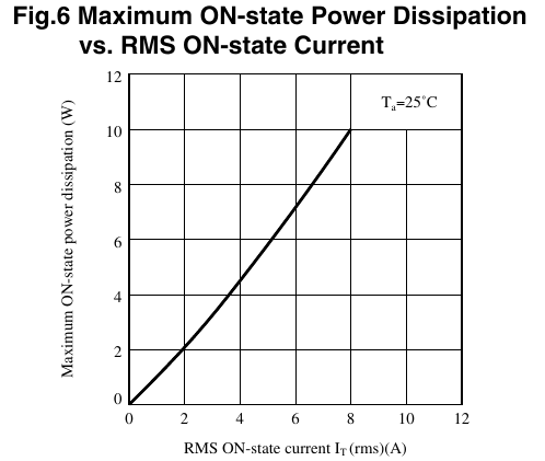
The S102S02 component is losing 10 Watts at 8 Amps load! Without a good heatsink it'll cook very quickly.
And it looks like the recommended added snubber is actually a requirement. The repetitive OFF-state peak current looks down right miserable. Don't use a varistor, they wear out apparently. Use a rated zenor diode, aka TVS diode. There are AC specific TVS diodes.
EDIT: Maybe I've misread it. That might be its parasitic current. Either way, spikes aren't going to be nice to it so a snubber is a necessity.

All right,
I found another box (just getting Man Cave usable) and - tada - resistors and transistors!
So I basically build what @"Francis Bauer" showed, alas without diodes, have not found that box yet.
Sadly no skills to make nice drawings like you.
Using a 2N3904 with 10K/1K resistors to ground to switch GND onto pin 4 (-). And 200 Ohm in between 3.3V and pin 3 (+).
Not sure about the snubber part.
I will switch AC for a 3 x 5V/10A Power Supply so there will be no frequent switching just on and off to have the power supply just running when needed.
Thanks a lot to all
After years of overtime I have now time for the Propeller again.
fun!
Mike
The diode is a throw-back for electro-mechanical relays, it is not needed for a SSR.
The transistor is optional, as the P2 can drive 200 ohms ok, but a transistor gives another degree of isolation.
Note the 10k/1k divider will have drive issues. You could use 2k2 series and 2k2 shunt.
Yeah, forget the transistor. The Propeller can drive 10 mA easy.
Still on the Bread Board.
I finally grooked what @evanh said regarding D1 and R2. Makes sense.
But, but I searched 2 hours to find the box with transistors. Now you say I do not need it...")
So basically what @Ariba did, just with R2 of 470 Ohm between Pin 3 and Pin 4 (Gnd)?
That easy? Cool.
Mike
yep.")