

struggling with understanding p2 manual.
 RS_Jim
Posts: 1,779
RS_Jim
Posts: 1,779
What I am trying to do is set a bank of 8 pins to have an internal 5k pullup. I then ground those pins selectively thru a dip switch. I want then to collect the results into a single byte to send along with my a/d results gathered on 8 other pins. I feel like I am getting too old to understand the manual without examples.
Jim
Comments
There are no internal 5k pullups, 1.5k, 3.3k, 15k are available (3.3k = 1mA mode). To init and read a dip switch on contiguous pins with 15k pullups:
CON
  DIPSW = 16 addpins 7      'pins P16..P23

PUB main() | s
  wrpin(DIPSW, P_HIGH_15K)  'init pullups
  pinhigh(DIPSW)

  s := pinread(DIPSW)       'read all 8 pins into s.[7..0]

  if s.[0] == 1             'test switch state
    'do something
Andy
I'd also config the low output strength in case a pinlow() is ever used during development:
wrpin(DIPSW, P_HIGH_15K|P_LOW_FLOAT) 'init pullups@Ariba
Andy thanks for your help. my code reads a little bit differently:
``
{ payload to transmit }
repeat idx from 0 to _payld_len -1
``
i am sending the data thru an NRF24L01+ ti be interpreted at the reader. I notice in your smple code an S. Is the . improtant?
Jim
The . is specifying a bit field for the variable. So S.[0] is referencing bit 0 of the S variable. It is a way to allow you test/access the individual bits in a variable.
If you send the switches as a byte, you don't need the .[bit] notation. This is only to test individual switches.
The
s == pinread(DIPSW)is not what you want, == is a compare operator. Try:{ payload to transmit } repeat idx from 0 to _payld_len -1 _payload[idx]:= adc.read(idx) idx++ _payload[idx] := pinread(DIPSW)Andy
Thanks Andy. Yes, I am sending the switch as a byte and a piece of test code shows me it is being sent correctly. Somewhere along the way I have managed to break my nrf link code so back to correcting that so I can proceed.
Today is my day off and the "honey do " list is lengthy so not sure the time will be available.
Regards
Jim
Hi Andy,
Well got the "honey do list" completed and able to get back on the project. Two things that have caught me un-aware: The first one is that when I do the code in the above example, I fail to get a reading of the DIPSW, the second is that it appears that it is reading dipswitch into the byte top down. I.E. what I expected to be bit 8 is bit 0.
I have made a temporary solution to the reading the DIPSW into the transmission stream by replacing idx with 8. I wonder if the idx++ is unnecessary, I should just read idx after the from to loop falls out. Maybe what terminates the loop is incremented 1 more time and falls out because it fails the count test. I currently have the 8 hard-coded in but if I ever want to change the number of ADC channels I will have to re-visit that. The next thing that I am concerned about, is that my adc results are not stable when there is no change on the input. I am wondering if I need to run the ADC in a separate cog and have the results averaged before putting them into the payload. I guess I need to address that issue with @JonnyMac as I am using his multichannel adc code'
Again thanks for the help with the switch reading problem.
I am begining to understand that better.
Jim
You can write:
{ payload to transmit }
  repeat idx from 0 to _payld_len -1
       _payload[idx]:= adc.read(idx)
  _payload[_payld_len] := pinread(DIPSW)
so the dip-switch will always be the last byte in the payload data.
You'll have to show me your code. The archive you posted in the other thread does not contain my ADC library, nor could I find the main file to see what's happening.
John,
I am sorry you felt that I made you feel like the bad guy. Flexprop did not include the top file of the program and I think I grabbed the receive version not the transmit version. The zip contains the name of the top file but not the file itself. Your program that I am using is : "jm_adc_multi_1.spin2". I attached the top file not zipped and the zipped archive. I am sure that I have some usage mistake. I value your contributions and do not wish in any way to make you seem like the bad guy.
Jim
edit: I went and looked at the other thread and I did indeed attach the RX end not the TX end of the link. My apologies to all.
The
hiconstant probably should be an integer rather than a float ...@evanh,
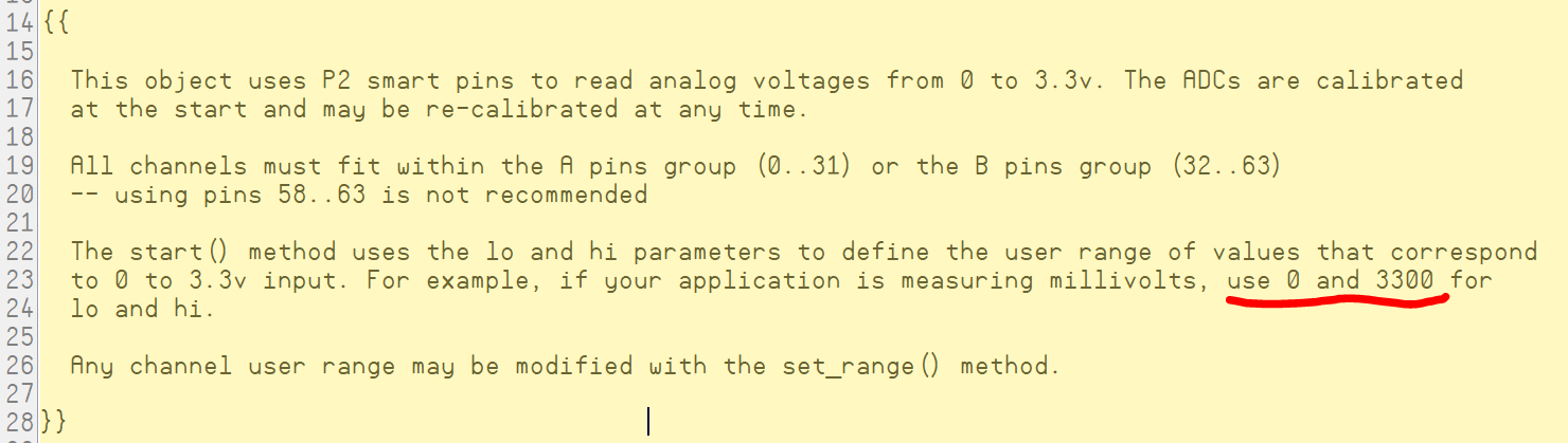
I think you are on to something. I wonder if John meant the lo and hi to be a range like 0 to 100? I thought it was the measurement range 0 to 3.3 volts.
Jim
the ADC code is hard coded to 2048 sysclock sample period ... 2048 * 3.3 / 5.0 / 2 = 676 ...
GIO's
loshould roughly be 1024 - 676 = 348VIO's
hishould roughly be 1024 + 676 = 1700EDIT: Oh, no, calibrate() does that part. Hi and Lo are applied on top of that ... Okay,
locan be left as 0. andhiis whatever integer value you want it to be. I would recommend a minimum of 1000.PS: Note: There is potential for negative readings when
lois set to 0.lo = 0 hi = 3.3The value for lo is fine; but 3.3 gets converted to a floating point type and you get 1_079_194_419 when compiled -- so with 0 to 3.3v in, you getting values from the read() method between 0 and over a billion; any small swings in voltage are going to create large changes in the return value (327_028 per millivolt).
There is commentary in the object about the lo and hi parameters.
  repeat ch from 0 to 7
    mv := adc.read(ch)
    bytemove(@_payload+(ch<<1), @mv, 2)
This would use 16 bytes of your payload for the ADC values. Reverse the process on the receiving end.
I'm human. You didn't say you were having trouble with your code, you said you were having problems and you'd have address the issue with me, as if my code was the problem. I work very hard to write quality code and vet it carefully before releasing (I'm not perfect, but I've only had a few snags). Far too often in the forums people blame the creators of libraries instead of looking to their own code (I guess that's a human thing, too).
Please delete that _1 version of my object and use what's attached (dated today). There are updates to the comments, hopefully preventing gotchas like you experienced, and I disallow the pins used for programming and flash/sd.
Jon,
OK, what am I doing wrong. I blew away all versions of that other jm_adc object and downloaded and installed the latest from your last post. After seeing some suspicious results, I went in and added a hex dump of _payload . A screenshot shows what I am seeing. I have measured the voltages on the input pin and they vary from 0.9 to 1.6 volts.
I added the test step in setup to make sure that the adc was starting ok. Your input will be much appreciated. Thanks,
Jim
How can I -- or anyone -- help you when your archive doesn't include the main program?
I've attached an archive WITH working code, and maybe this will help. It reads eight ADC channels and writes them to a 16-byte array (like your packet). I did a screen grab and and added highlighting to help make things clear. Note that I only attached one pot to the Eval board and set it to Vcc. The other pins were left floating.
Remember that Propeller values are Little Endian -- I highlighted this in the raw reading and the packet bytes.
I don't use FlexProp, but did test, and as you can see, it works there, too.
To be fair, I think @RS_Jim is trying to create the archive with a beta version of FlexProp, and it appears the zip library I used is not completely compatible with Windows built in zip handling . The file is there in the zip archive, but not visible under WIndows.
Jim, as I suggested earlier I think your best bet is to make a new directory and copy all of the files you're using into that directory. Then they're all in one place (so you know what you're getting) and zipping them up manually will be much easier. I also suspect the automatic FlexProp zips will work better in that configuration, but for now you should view those with suspicion.
FYI the built in Windows (un)zip library is a binary blob created a long, long time ago.
So newer open source zip libraries most likely do not default to a compression that this older code can recognize.
Without getting overly political, the easiest course of action is to "sacrifice" some compression efficiency for the sake of compatibly.
It's like the British making fun of how Americans pronounce aluminum, when they themselves changed it later. The unzip library was correct at the time, until it changed.
What I know:
ZIP_DEFLATED is the most compatible compression method.
Filenames cannot contain the leading slash typical in Linux.
Filenames cannot contain <>:"/|?*
Filenames and folders cannot end with a space character or the period .
Edit2:
Yep it is the \home that is causing the problem. Cannot have a leading slash.
Ok, I really appreciate all the assistance I am getting here. @ersmith is correct in that I am using a beta version of flex prop.
I am working on an 8 year old laptop that was windoz 8. I have since converted it Linux Mint v20 that is fully updated. The laptop has also been converted to an ssd so it runs pretty briskly. I have no windows capability unless I run everything under wine. When I run it exactly as you sent I get a totally blank screen. I changed the terminal programs and what I get is the attached. I just found out there is a bug in te version of flexprop I am running so attempting to upgrade that. Will continue when that is complete.
Jim
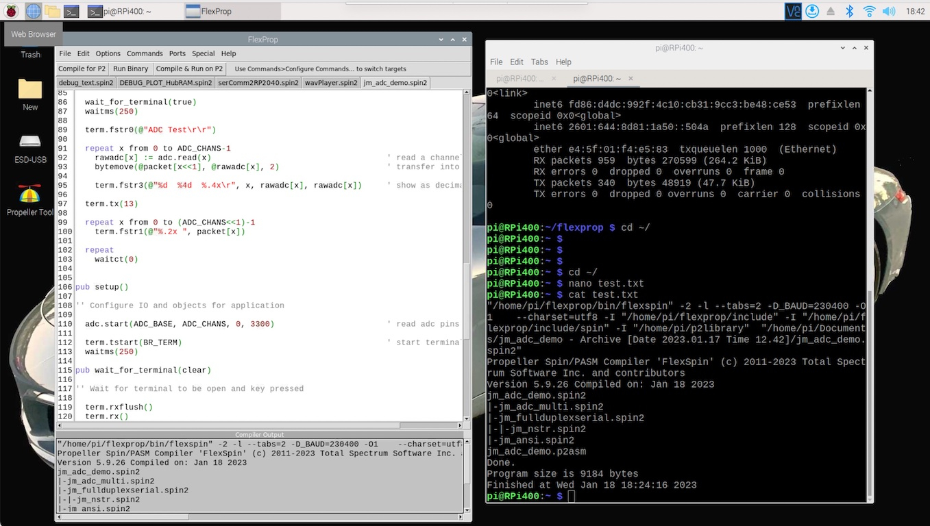
I have this exact code running on a Raspberry Pi (yes, Linux). No edits needed, it just compiled & ran. I'm running flexprop 5.9.26).
Here's the compile & run, and shows the Compiler Output text (in the flexprop window) had been selected (and copied from flexprop). On the right side, is a Terminal window showing that the text was pasted into a file named "test.txt" in the nano editor. Then, the text was displayed with the cat command. That text will be helpful in debugging compiler issues (copy that into your posts):
dgately
I have demonstrated that my code works in FlexProp under Windows, and Dennis demonstrated the same is true with Linux.
Note that I'm using the FlexProp PST terminal. It was a nice add by Eric that makes programs written for PST work without changes. You're using the ANSI terminal. You can change that in the Options menu:
I'm going to bow out of this discussion now. Good luck with your project.
Ok I have the adc demo running as expected. I figured out my problem was my board config is different than what Jon is running. Once I edited his demo with my boardconfig it ran as expected. Yes, things are gobbldygook when you are using a config based on a 20MHz xtal on a board with a 25MHz xtal. as soon as I added the board config info into the con block the demo worked. Thanks to all for their help, Jon for the demo and dGately for the reminder about pressing "any key"
Thanks again all.
Jim