

Weird "off by one" result when hammering hubRAM **Fixed - It was my board layout**
 ke4pjw
Posts: 1,334
ke4pjw
Posts: 1,334
So, in my light controller project, I have been chasing this weird "glitch" that occurs in the pixels. It is an off by one. What's really weird about it, it only manifests itself when specific color levels are displayed. I have found that Red, $FB_00_00, will cause the glitch to occur. It will cause the pixels to display blue very briefly. In my debugging I have found the following facts surrounding the issue.
Configuration Information:
A single cog writes to hubRAM in bytes.
3 cogs read from the hubRAM in longs. (Though in testing, using RDBYTE, the problem still exists)
When only 1 cog is reading from hubRAM, the issues does not exist. When two cogs read from hubRAM, the issue occurs. When three cogs read from hubRAM, the issue is prominent.
It does not matter how many reads are occurring in the read cog.
I have found that the issue does not manifest itself due to a timing issue with the pixel outputs.
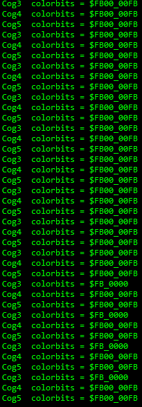
What I found is that the data that is read from hubRAM changes from $FB00_00FB (The last FB is omitted by my program, I only need 3 of the four bytes) to $FB_0000
I think the fix will be to move all pixel output operations into a single cog, unless anyone has a better idea as to how to keep this from happening.
Comments
This sounds strange. You are sort of saying that doing multiple reads are corrupting a given write to HUB? If the bad reader COG reads the same data address again, is it still bad, or does it fix itself automatically?
Might want to check that the P2 power is stable. HUB accesses are meant to be atomic.
Are these individual accesses all long aligned in HUB RAM or do they spill over a long sometimes?
This is "out there", I know. Very strange. I can't think of anything in my code that would cause this condition, as the read cogs do not write to hubRAM. Simply starting the cogs causes the issue to appear. This happens in testing across multiple hardware platforms with various Edge cards and power supplied.
These are not long aligned reads. I took that out of the mix in my testing, by just pulling the first byte of the long (replacing RDLONG with RDBYTE), which resulted in $00 being returned when the glitch appears.
I am running over 180Mhz, so I don't know if that plays into this mix. Typically you only have two cogs interacting with an area of hubRAM, one writing and one reading, so this use case is a bit unusual.
I am racking my brain trying to figure this out. Why would starting these cogs result in this issue? Maybe it is affecting the writing cog in some way, such as affecting access times to the pins, or something to that effect. It's very strange.
Try to make a simplest test program which still does the glitch and put it here. This is an interesting thing, but we don't know when and what is read/written.
I had (and still have) a glitch in NeoYume, where something doesn't stabilize "on time" in the chip and this is only on the cog #0 of the P2 in my P2-EC32 board. Other cogs and other P2s work as expected.
Can you test the problem on another P2 chip?
Be sure you have given enough stack space for each cog.
@pik33 The problem occurs on the 7 different P2 Edges that I have. Unfortunately the program is complex. I will try and strip back as much as I can by stopping cogs that can be removed. The program uses all 8 cogs. The issue becomes apparent when the 7th and 8th cog is started.
@whicker the only cog that I gave stack space to is the watchdog cog, and I can't even remember how/why I did that. What's best practice?
Also, another thing I should mention: If the cog that writes data does not write data to the area of hubRAM used by the reading cogs, the glitch does not occur. Only when it is actively updating the pixel buffer does it happen.
It may be possible that the glitch is occurring and I can't catch it until enough reads are happening to slow down the hub. I need to 100% validate this. You can't place conditionals on debug statements, so it is going to be difficult to catch.
Have you considered a double-buffer setup? I use this in my P1 WAV player, but then, I only have one background cog reading the buffers. In my case, when the background is done with a buffer it sets the length variable to zero which flags the foreground to refill it (if there is data left in the file). Maybe you could use a byte with flag bits to indicate that all background cogs are done with a buffer and then you could refill it and mark ready by clearing the flags.
This does sound like a stack space issue...
It is highly unlikely that there is a flaw in hub memory access.
You could also print the address of the variable you are trying to read from too in each COG. Maybe the address you are using is being corrupted by a bad stack,or something else increments/decrements it etc. Might give more insight...
So it is unclear if write is failing, or read ? If all GOGs read the same value, that makes write suspect.
That's a highly correlated failure, (not random bits changes) which also points to a write problem.
If you are writing in bytes and reading longs, a skew error of off by one byte would match those symptoms.
A test that writes longs could be useful ?
Thank you all for your insight and suggestions. I will take a look at each of these.
If you are so inclined, I did a 30 minute video showing the issue and how I can cause it, or make it go away.
Something to note, the glitch only appears to happen with very specific, large values. FB_00_00 demonstrates it best, but other values can cause it to happen.
Update: I think this may be some type of interference between the pins used for ethernet and the pins used to drive outputs 17-24.
Not sure if I have a logic analyzer fast enough to "see" if that is the case.
I wonder if this is my problem:
                 altsb     tx, #outa                            ' What is the base PIN?
                 setbyte   #$FF                                 ' Turn them all on, because pixeldata always starts with a 1
Where tx is a value > 31 on the cog that causes the issue and the ethernet driver is located on P15-30.
Looking at this, I am not sure how it even works now.
I thought you were reading actual bad values from HUB and can print it out. Toggling IO pins affecting other pins could affect your LED outputs but shouldn't affect HUB memory unless the writer COG also sources this data originally from the Ethernet pins. Do you CRC test all your packet data? Corrupted Ethernet packets being read could be detected that way.
@rogloh CRC is checked by the hardware that I am using. If the CRC is bad, the packet is discarded. It never makes its way into the device's buffer I am reading from.
I suspect the cog driving outputs 17-24 is somehow modifying the pins that are used by the ethernet cog. This is causing an off by one on occasion. Once you setup what part of the buffer you want to read out of the ethernet chip, you can simply toggle the RD line and it will auto increment. I suspect something I am doing is causing that to toggle, and that's why I am getting the off by one. I have found where other pins are being manipulated when the cog starts up, and I suspect that is where the problem is.
More updates this evening.
Ok there is obviously more to your system than meets our eyes as to what your software actually does. You are hopefully onto the root cause now at least.
Are these large values that cause trouble sent over the pins top-byte-first? $FB000000 may cause a lot of pins to go high at once and maybe, due to PCB layout, some spike is induced in the READ line, causing an extra initial READ pulse.
New findings from last evening:
Extremely high correlation between the lower 4 bits of the data in the ethernet packet and glitching. Examples FF,EF,DF,CF,BF,AF,9F,8F,7F,6F,5F
Glitching occurs only if outputs enabled for 22-24. (P38-P40)
@cgracey I had the same thought. I added 10K "pull ups" to ensure that RD would not be pulled low due to an induced transient of some type. (The ethernet is cogless, and between operations, those pins float) This had no effect. I do notice that when the glitch occurs, it does happen in the middle of reading the data from the buffer and usually is only visible after 25+ pixels were sent data properly.
When I did the board layout, I tried keep the output paths on the opposite side of the board from the ethernet paths. I also tried to run them at right angles to each other with as little in parallel as possible.
Possibly a power glitch? The ethernet is powered from V16-23, but data pins are on P24-P31. But that doesn't correlate with any of the ways I know how to cause the glitch.
I feel like renaming it "Blitzen 21" and calling it a day. The symmetry I need in my brain won't let that happen, LOL.
I am going to twist this thing inside out until I figure it out.
Your data lines run at right angles but they cut the ground plane in half. If it's not crosstalk it might be ground bounce. I'd try to add ground bridge wires to re-connect the separated ground plane "islands". You could also reduce the drive strength of the outputs to reduce the switching slopes and currents. 1.5k or 1mA output modes should be fine.
You can get clock bounce glitching crosstalk, where many data pins change and enough energy is injected into a long clock/WR line, to bounce it enough to register as a 'bonus' clock/WR pulse, and voila you have a off-by-one error.
Because you can be talking about ns impulses, adding small parallel C or series R to the clock line, right before it hits the target clocked device can help.
Those traces for ports 22-24 run parallel to the main CPU power trace with high currents after the fuse and before any chance to filter noise. Maybe add a cap in parallel across D1 to see if it helps - although it's after the parallel portion of these trace, but could be worth a simple test.
Also notice that ports 22-24 are the closest signals to the ends of the traces for D0-D7 going in your Ethernet module. There's also only a skinny bit of your ground plane left there between that Ethernet module and the main Edge power line, perhaps it's insufficient for much shielding of crosstalk.
Thank you call for your responses! I believe I have it licked. Here is my process so far:
Tried adding various new low impedance paths to ground for the ethernet, Edge, and non-inverting buffers. Result: No effect.
Tried various caps (.1uf - 1uf) across D1. Result: No effect.
Tried various caps (.1uf - 1000uf) across power to ethernet. Result: No effect.
Tried small value caps across RDn and ground. Result: P2 could not communicate with the ethernet chip.
Tried 3K resistor in series with RDn. Result: P2 could not communicate with the ethernet chip.
Tried 1K resistor in series with RDn. Result: P2 could not communicate with the ethernet chip reliably.
Tried 75 ohm resistor in series with RDn. Result: Much reduced glitching.
Touched CS pin. Result: All glitching stopped
Tried 473 ceramic capacitor across CS and ground. Result: All glitching stopped
Jumpered across 75 ohm resistor in series with RDn. Result: Glitching returned.
I am not sure the path forward at this point. Maybe a small board between the ethernet and the main board.
Again Thank you all!
Terry, make sure that any critical digital signal is always driven from the P2, rather than relying on a pullup. Anything left at high impedance is subject to parasitic capacitive and inductive attack from nearby high-speed signals.
Yeah, this looks like noise on your CS line. I think I'd put a pull up or pull down resistor there... Maybe 1k (or 100 Ohms even to be sure, 10k should be good enough).
Capacitor would probably work too, as you've shown. Put it close to the Wiznet module...
And, like Chip said, make sure you are actually driving the pin state. Looks like the Wiznet has a 75 kOhm pullup on CS. Some drivers might be relying on that, but you can't here...
Sounds like good progress")
You could also try 120~220R series R ? Values toward and above 1k will be as you found, too large and they distort the pulses.
473 is a relatively large value, if touching CS is enough, you can go much lower. 100pF ballpark ?
You could also try lighter pin drive (no C needed) on aggressor nets, which CS appears to be.
Chip, that was an unfortunate design choice on my part. I wanted the ethernet driver to be cogless, and in order to do that, I have to float the pins when not accessing the Wiznet. Locks are used to ensure more than one cog can't access the Wiznet at the same time. So that means that at some point, the lines are floating. It made writing the ethernet driver easier. What is weird is no operations happen unless CS is low, Going low is the first thing that happens and going high is the last thing that happens before being set to float. Just wild that it manifests the way it does. Live and learn")
This can be solved in your code!
All cogs' pins' OUT bits get AND'd with their local DIR bits, then all those 8 cogs' signals get OR'd together to determine the final OUT bit going to the actual pin. If any cog makes a pin output a high, that pin will output a high. You need it so that if any cog makes a pin low, it goes low, but is always driven.
Use WRPIN to make the output inverted on the CS pin. Now, all cogs can keep CS as a low output and the actual pin will be high. When any cog wants to make the actual CS pin go low, they set the pin to high. This way, the CS will always be driven.
@Rayman I tried a 10k pullup. No effect. I'm just glad I got it working.
@jmg I am looking at the hardware manual. I will try and grok the WRPIN configs. I am all about a software solution, so I will take a swing at it!
Something that is really bothering me is the way I am driving that last group of 8 pins.....
                 altsb     tx, #outa                            ' What is the base PIN?
                 setbyte   #$FF                                 ' Turn them all on, because pixeldata always starts with a 1
tx is set to 4 (P32-P40), but the source is #outa instead of #outb. How is that even working?!?!? I just added the extra code in the main program to start the cog that sends data to the last group of outputs, full send. It worked so I never reviewed it. Now that I look at it, how does it even work?!
@cgracey Oh! I think I asked someone about this awhile back, but dismissed doing it for some dumb reason. Most likely because there were a lot of touchpoints to do it. OK, I am going to start digging into this, this evening! Thank you!
WRPIN ##$00004000,#cs_pin
Just add that and use...
DRVL #cs_pin 'drive cs high
DRVH #cs_pin 'drive cs low
All cogs that are not talking to the Wiznet do a DRVL, while the one cog that IS talking to the Wiznet does a DRVH.
Better to use the symbolic
P_INVERT_OUTPUTthan a magic number...