Ok, let me redefine the problem then which basically amounts to how to measure a change in the capacitance (either between a given pin and a ground plane or mutual, between the pins) with the P2. The simpler the method the better.
I just need to distinguish between "on" (finger detected) and "off" (no finger present) states. No fancy tracking required.
I'm not all that familiar with how any of them are done. I suspect you've got multiple approaches to choose from electromechanically.
That Goertzel demo board is a valid approach where there is two electrically isolated plates next to each other and your finger acts as increased capacitance - Coupling the signal from one plate to the other. The receiving amplitude increases as finger gets closer.
Another approach could be with a single plate. Here your finger's capacitance acts as a grounding load that dampens the transmitters output. Again amplitude is measured, but it decreases.
Both cases need an AC output from the transmitter. Receiver measurements can be of rectified peak.
In any case looks like I need two pins to have a single capacitive channel anyway, right ?
I shall study the P2 docs more, obviously. Thanks for the hints.
An alternative solution would be to use some dedicated capacitive touch controller (TI's msp430fr26xx series seem to be perfect for the job) but that is something I'd like to avoid if possible. I do not need that many channels (min 5 max 8) so I might get away with the P2 alone.
Thinking about it, the simplest approach is just treat it as a R-C timer curve. So not your typical AC waveform.
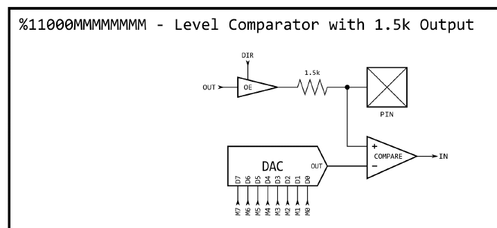
It should be possible for the Prop2 to get away with a single pin but will need proving. There is two pin modes that could work. CompDAC comparator mode is the simplest in logic but the fixed 1500 resistor is likely too strong so limits sensitivity. The other mode is ADC with weak logic output. This one will need sampling and computing so is processor heavy.
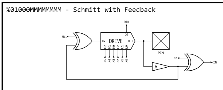
Oh, duh, an AC frequency would be produced from inverted feedback. If the capacitance changes then the frequency will too. And a smartpin could tell you the frequency.
Thank you, sir.
The last one is the closest in principle to what TI does so in theory it should work. Seems to be the most promissing of the three. Needs to be verified in practice, of course, because the frequencies generated can probably be quite high (or maybe not, I don't really know yet).
I'm hopeful I no longer need an additional cap touch controller.
I think, for Goertzel one single output can be used together with several inputs. So n+1 pins are needed. A dedicated cog would be needed probably, because Goertzel uses LUT and the streamer, which gives a conflict with hub assembler execution. Well, perhaps I should experiment a little bit with Goertzel mode, because this seems to have several interesting possibilities....
Edit: Reread the Goertzel mode docu. To scan different inputs, the modes and pins have to be changed by program, I think.
(I begin to believe, that the Goertzel functionality can be achieved more easily -at least for lower frequencies- using dac, adc (raw bitstream?) and the cog, which is blocked anyways for many usages. (???) )
There was the Parallax Quick Start board, using capacitive touchpads with one pin, maybe look up the schematic, source was in spin, but you should be able to convert to Forth.
@msrobots said:
There was the Parallax Quick Start board, using capacitive touchpads with one pin, maybe look up the schematic, source was in spin, but you should be able to convert to Forth.
Mike
Are you sure it was actually capacitive touch ? I think it was just touch buttons (resistive touch).
Comments
This is done in Assembler/smartpin using the Goertzel feature of P2. So search for this word.
I do not know of a TAQOZ implementation.
The Goertzel demo code for the Prop2 is not for touch so much. It's for tracking your finger position floating above the add-on board that comes in the kit of accessory Eval add-on boards. - https://www.parallax.com/product/p2-es-eval-board-accessory-set/
Ok, let me redefine the problem then which basically amounts to how to measure a change in the capacitance (either between a given pin and a ground plane or mutual, between the pins) with the P2. The simpler the method the better.
I just need to distinguish between "on" (finger detected) and "off" (no finger present) states. No fancy tracking required.
I'm not all that familiar with how any of them are done. I suspect you've got multiple approaches to choose from electromechanically.
That Goertzel demo board is a valid approach where there is two electrically isolated plates next to each other and your finger acts as increased capacitance - Coupling the signal from one plate to the other. The receiving amplitude increases as finger gets closer.
Another approach could be with a single plate. Here your finger's capacitance acts as a grounding load that dampens the transmitters output. Again amplitude is measured, but it decreases.
Both cases need an AC output from the transmitter. Receiver measurements can be of rectified peak.
In any case looks like I need two pins to have a single capacitive channel anyway, right ?
I shall study the P2 docs more, obviously. Thanks for the hints.
An alternative solution would be to use some dedicated capacitive touch controller (TI's msp430fr26xx series seem to be perfect for the job) but that is something I'd like to avoid if possible. I do not need that many channels (min 5 max 8) so I might get away with the P2 alone.
Thinking about it, the simplest approach is just treat it as a R-C timer curve. So not your typical AC waveform.
It should be possible for the Prop2 to get away with a single pin but will need proving. There is two pin modes that could work. CompDAC comparator mode is the simplest in logic but the fixed 1500 resistor is likely too strong so limits sensitivity. The other mode is ADC with weak logic output. This one will need sampling and computing so is processor heavy.


Oh, duh, an AC frequency would be produced from inverted feedback. If the capacitance changes then the frequency will too. And a smartpin could tell you the frequency.

Thank you, sir.
The last one is the closest in principle to what TI does so in theory it should work. Seems to be the most promissing of the three. Needs to be verified in practice, of course, because the frequencies generated can probably be quite high (or maybe not, I don't really know yet).
I'm hopeful I no longer need an additional cap touch controller.
I think, for Goertzel one single output can be used together with several inputs. So n+1 pins are needed. A dedicated cog would be needed probably, because Goertzel uses LUT and the streamer, which gives a conflict with hub assembler execution. Well, perhaps I should experiment a little bit with Goertzel mode, because this seems to have several interesting possibilities....
Edit: Reread the Goertzel mode docu. To scan different inputs, the modes and pins have to be changed by program, I think.
(I begin to believe, that the Goertzel functionality can be achieved more easily -at least for lower frequencies- using dac, adc (raw bitstream?) and the cog, which is blocked anyways for many usages. (???) )
There was the Parallax Quick Start board, using capacitive touchpads with one pin, maybe look up the schematic, source was in spin, but you should be able to convert to Forth.
Mike
Are you sure it was actually capacitive touch ? I think it was just touch buttons (resistive touch).
you might be right. But they did work quite fine.
Mike