Charitable donation for memory and display boards
Think found a way to send out the 24 MB and 96 MB PSRAM boards we're using for @Wuerfel_21's MegaYume and NeoYume and also some other emulators.
They are also good as a VGA buffer or general purpose RAM thanks to the driver from @rogloh
Can't take cash (long story), but think can use verified donations to Red Cross instead.
Just put some info here: http://www.rayslogic.com/DonateForGear/P2Eval_Charity_Gear.htm
These boards are compatible with P2 Eval board style headers.
Update 28Aug22: 2.4" TFT Display board now available.


Comments
Mmmh, finally some more people get to bask in the glory of the ridiculous 96MB expander.
Should probably get support for that board in MegaYume ready for primetime then.
Ray,
The layout of the 96 MB add-on needs work. I haven't tried to prove the main issues but evidence so far is the 96 MB layout is not healthy at all. I'm highly suspicious of the ground plane in particular, the header ground pins don't have wide conduction path. I think ground bounce is probably the biggest problem.
You might need to check your site’s security certificate as all my browsers are throwing errors on it.
I had the same problem.
I fixed the SSL issue.
Also, added a note to memory boards like: Note: Boards are tested by starting several games in MegaYume NeoYume. They have not yet been proven to be flawless and may have hidden errors.
Yea, as was said in the other thread, room for improvement. But as is, the board runs perfectly stable at 338MHz/3, so it's not that big a deal.
Unrelatedly, probably a good idea to put some links and instructions for the emulators on the site.
Better improved sooner rather than later if there is going to be more of these boards made.
@Wuerfel_21 Added those links and also one to @rogloh's driver thread.
I think the instructions for using the 24 MB and 96 MB boards in your MegaYume and NeoYume github sites are pretty good.
Probably should add a specific example for how to use @rogloh driver alone or for VGA separately though...
Although, I think you have this in your memstuff folders too.
I really appreciate the intention, but out of principle, I won't donate to that corporation even if the funds were given to me to do so. I would MUCH rather buy a 96MB one outright.
Did you use the 96MB board on the KISS0001 board? If so, what clock and divider were you able to run the KISS board & mem board at?
ModEdit: Negative inappropriate (and unnecessary) opinion removed.
Just got the QWIIC connectors needed to complete the 2.4" LCD boards.
The cogged version of the driver is crazy fast, compared to the P1 version:
QWIIC connectors soldered on, so these 2.4" TFT toushcreens (with Nunchuck and QWIIC) are now available see it here.
Boards that use 2 connectors on the EVAL board will not fit on the KISS boards, the distance between the connectors in the KISS boards is closer together. It is not too difficult to make an adapter though (preferably to be used on the outside set of connectors), although I have no idea how that will impact the RAM board's speed and reliability
@rosco_pc If the idea is to play MegaYume or NeoYume, maybe I'd try the 24 MB board first and see if it works. I'd suspect it doesn't, just because none of my boards do. It's some crazy clock rate, way beyond spec. But, maybe I'm wrong. In that case, an adapter board could be made pretty easily...
Adapter board would be useful for having the KISS board work with the display modules I'm working on too...
Have you tried making one with beefier regulators yet? That was theory IIRC.
@Wuerfel_21 I guess this is on topic, because would like to add this to boards here, hopefully after getting it to work with Mega/NeoYume.
Previous attempt had two 1A regulators with the 1.8 V being fed from the 3.3 V.
This got very hot running Mega/NeoYume.
Latest version (2e) has 500 mA switching regulators with both 1.8 V and 3.3 V fed from 5V supply.
These stay cool, even running Mega/NeoYume.
I actually thought had success on first try because it runs fine for several minutes. But, then goes off the rails.
I'm pretty sure it's thermal issue on P2 chip.
Blowing a fan on it helped, but still died after ~30 minutes or so.
I'm thinking about trying same design with 2 oz or 3 oz copper...
You may need to step up your capacitor game.

Consider how many the Parallax designs have, directly on the power pins:
They also have these vias underneath the chip to sink the heat. (Can't tell if you have those)

Other than that, I guess I'll ping @VonSzarvas to share his design wisdom (or just a straightup known-good layout)
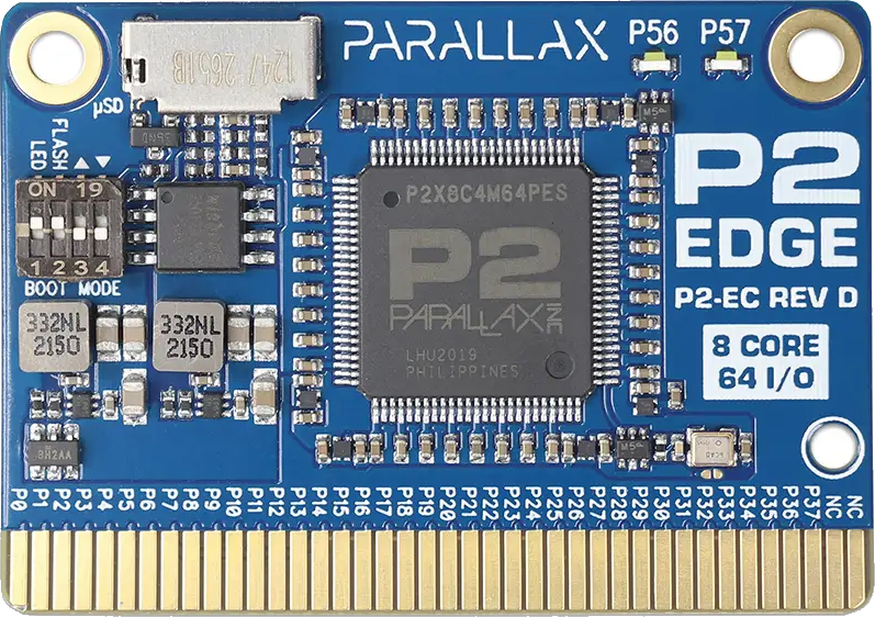
Ada's game emulators will need excellent heatsinking. Basically, she's tuned them to work with the reference boards, namely Eval and Edge. The Eval boards are best at this, so anything less than the Edge's heat transporting ability won't cut it.
Easy possibility: try and see if sticking a heat sink to the chip does anything. Going through the plastic case doesn't conduct as good as the ground pad, but perhaps worth a try.
I would rather try taking a fiberglass pen after the back side of the edge to get to the copper and stick a heatsink to that. Those vias should go right to the big solder pad on the bottom of the chip.
I’m thinking the evaluation board has 4 layers of 1 oz copper. Need 2 oz copper with 2 layer board to match…
About the layer thicknesses you mentioned @Rayman , I've gathered some details:
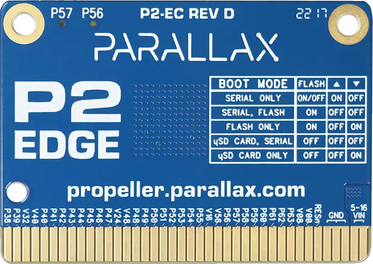
P2-EC RevD is 6 layers, with 2oz on the outer layers and 1oz on all inner layers
P2-EVAL RevB is 4 layers, with 2oz on the outer layers and 1oz on all inner layers
In a perfect world you'd want to get as thick as you can make the copper layer on the bottom (thermal slug), and stacked/plated to allow as thick as possible plating inside the vias under the chip, whilst keeping those holes <0.3mm ideally (to prevent solder paste issues).
The via plating will be improved by whatever you plate the bottom layer, which would typically need to balance with the top layer; you will be into cost-vs-capability-vs-chaos compromises by this point! Thicker copper will also increase minimum width/space specs, which may not impact a solid bottom layer (if you have one), but likely will impact the opposite layer.
@Rayman,
I just received the 2.4" TFT touchscreen boards and they work great.
Unfortunately your website is down again, so I can't download all of your demos. :-(
I just sent you an e-mail, but I don't know if your e-mail works while your website is down.
It's up now. Don't know what's going on with my website hosting service...
Seems like it's down half the time I've checked in the last week.
Used to be very good...
I can email the stuff if it goes down again...
@VonSzarvas Thanks. That probably explains its. I'll try 3oz copper on both sides soon.
If that doesn't work, either give up on >300 MHz or try 4 layers.
Tested out the Rev.C. Edge with MegaYume and NeoYume just now.
One combination that works is the mini-breakout with the 24 MB module on basepin P0.
Doesn't work at all with the large breadboard.
96 MB module also doesn't work in any configuration I tried.
Doesn't work on any other basepin (but, I think it's that way on the Eval board too).
Looks like the Edge module gets too hot for NeoYume.
It plays for a couple minutes, but bad parts of video lines start showing up and then it goes off the rails.
So, I'm guessing my board with 3 oz. copper may be in a similar boat, we'll see...
As a reference point, I've been using RevD and that was fine for a good session of play. Can't recall how long a "good session" was .. but probably an hour at least.
RevD has close to double the GND copper volume of RevC to help with overclocked applications.
With your RevC, would it be practical to add a heatsink or run a small fan nearby whilst you're experimenting ?
@VonSzarvas Was that with MegaYume or, hopefully, NeoYume?
It most certainly should work on any basepin. I use the 24MB board on base 48 of my eval board. Have you thoroughly fiddled with the tuning? (DELAY and SYNC_DATA mostly).
I haven't fiddled at all. I'll try a bit...
I might need to make it super bold in the documentation: The given tuning values only apply to the exact hardware configuration described. Even a different basepin may require different delay compensation.