

Gyroscope BNO055 I2C problems [solved]
 ManAtWork
Posts: 2,367
ManAtWork
Posts: 2,367
I have tried to connect this 9DOF accelerometer/gyroscopy/compass module to the P2 with I2C communication. The signals look good but the chip does not respond (ACK=high). I use this board originally designed for the Arduino. I have connected the GND, +5V, +3.3V, IOREF, SDA and SCL lines with jumper wires.
The board has a 3.3/5V level shifter but if I connect IOREF to 3.3V it should also work with 3.3V signals from the P2. I have verified the levels. The scope screenshot shows the actual signals at the BNO055 pins, trace 1 = SCKL and trace 2 = SDA.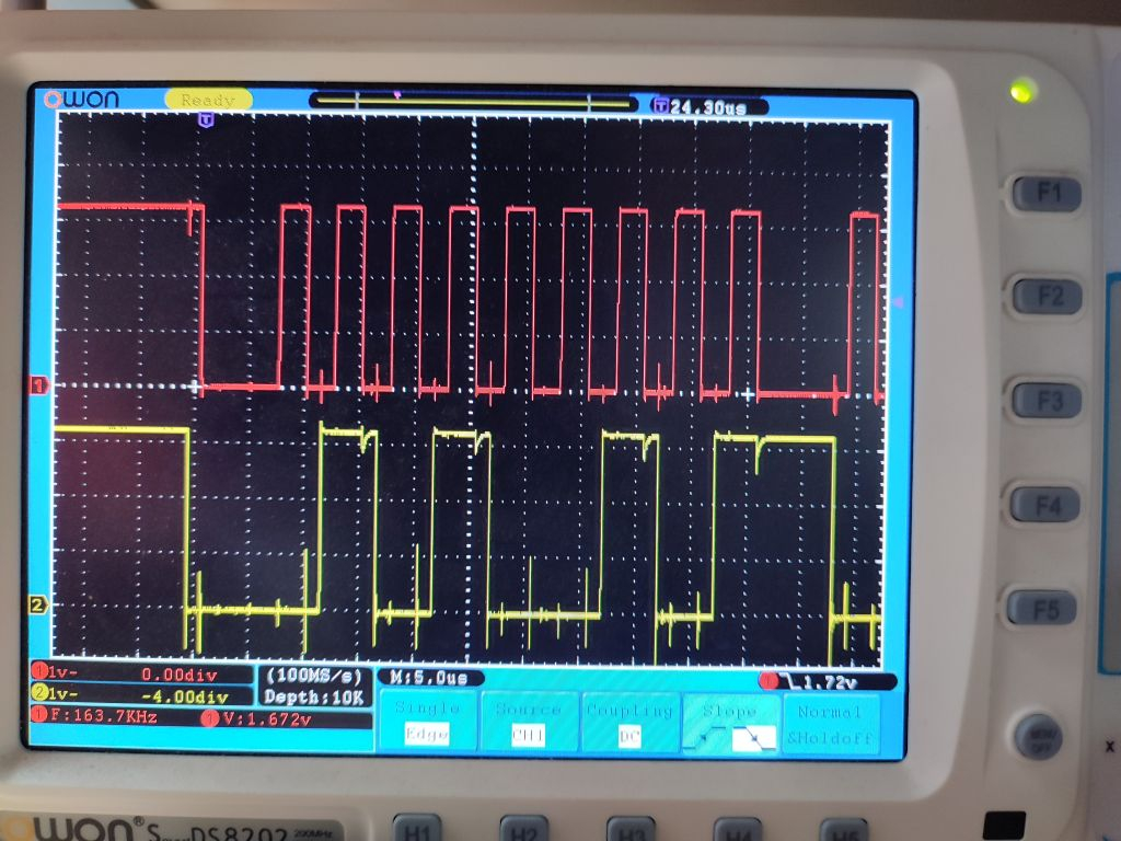
I have also verified that the I2C address is set to $29 (ADR jumper set to 3.3V). I have also tried the $28 address, same result: no ACK, all registers read $FF. And yes, I know that the 7 bit address has to be shifted left by one bit, so the actual value uf the first address byte is $52 for writes and $53 for reads.
I've used the search engine and found out that many others had the same problem.
https://forums.parallax.com/discussion/comment/1491760/#Comment_1491760
https://forums.parallax.com/discussion/163592/propeller-activity-board-simpleide-adafruit-bno055
https://forums.parallax.com/discussion/164372/bno055-sensor-i2c-reading
Someone mentioned clock stretching could cause problems. But I googled that and it is said that clock stretching means the I2C slave delays clock cycles by holding SCL low. I can't see that happen on the scope. I've set the clock speed to 200kHz instead of 400kHz but it makes no difference. All timing requirements of the BNO055 data sheet are met, I think.
As the P2 driver for the BNO055 is working it could have been something about the timing as the Spin I2C driver is a lot slower than the P2 smart pin implementation. But slowing down the timing doesn't help. Any ideas?
Comments
I have had good luck with I2C on the P2. You might try the attached program which I use when connecting new devices.
The program lists all devices that respond in 8- and 7-bit formats.
My P2 I2C driver uses inline PASM so you can set the speed. It also handles clock stretching -- at least on the one device I've encountered that uses it -- but you will only see clock stretching on reads; you should be able to ping any device with no problem.
Thanks a lot, Jon. I've tried it and it displays this:
P2 I2C Devices
-- dddd_aaa_x (8-bit) format

    00 02 04 06 08 0A 0C 0E
    -- -- -- -- -- -- -- --
10  .. .. .. .. .. .. .. ..
20  .. .. .. .. .. .. .. ..
30  .. .. .. .. .. .. .. ..
40  .. .. .. .. .. .. .. ..
50  .. .. .. .. .. .. .. ..
60  .. .. .. .. .. .. .. ..
70  .. .. .. .. .. .. .. ..
80  .. .. .. .. .. .. .. ..
90  90 .. .. .. .. .. .. ..
A0  .. .. .. .. .. .. .. ..
B0  .. .. .. .. .. BA .. ..
C0  .. .. .. .. .. .. .. ..
D0  .. .. .. .. .. .. .. ..
E0  .. .. .. .. .. .. .. ..

Devices: 2
-- $90 %1001_000_0  (7-bit: 0x48)
-- $BA %1011_101_0  (7-bit: 0x5D)
$BA is the address of my absolute pressure sensor and $90 is the differential pressure sensor. The BNO055 doesn't respond, even not at 100kHz.
I'm pretty sure I've connected everything correctly. IoRef might have been floating for a short time because my jumper fell off but that affects only the P2 side of the level shifter. The sensor side is hardwired to 3.3V so it shouldn't have damaged anything.
I wish I had something helpful to offer as I've tried this chip too, with basically the same experience you have had. Unfortunately I somehow bricked both units I bought, doing not much more than you have. Chances are we've searched some of the same threads. FWIR, a few other people using other platforms ended up at the same point. All I can say is to proceed very carefully, and heed others' warnings about using clock stretching (maybe to be extra cautious, wait for the clock to actually go high before proceeding, after any time it transitions, not just the usual points clock stretching is implemented). Hopefully you'll end up having better luck 🤞
This could possibly be of some use: https://forums.adafruit.com/viewtopic.php?f=19&p=556191
User gammaburst there looks to have implemented a bit-banged I2C engine on the Pi because the hardware transceiver didn't support clock-stretching (or was broken). Maybe it could be trawled through to see if Jon's code implements the clock-stretching in the right places for this chip. Someone mentioned it expects it for the ack bit. A little unusual in my experience, but not the first time (Sensirion's SCD30 needs this, too).
Hi
I have a cheap ebay version of the BNO055 and it seems tot work well- but I use the serial uart mode. It might be worth a try just to verify the chip is good- just need to strap ps1 HI and ps0 LO (for I2C both strapped LO) then SDA becomes TX and SCL becomes RX.
Dave
Thanks for the hints. I don't think it has anything to do with the clock stretching. In the scope picture in post #1 I see a start condition followed by 9 clocks with perfect 50% duty cycle. If the BNO055 issued clock stretching one of the SCL low phases should be longer or there should be some visible sign of bus contention (both units drive the line to opposite levels resulting in an intermediate level). But nothing like that happens and there should be an ACK bit at the 9th SCL pulse.
So the only explanation I have is that the chip is damaged. It was brand new in a sealed box and I was very careful connecting everything right. I connected the +5V first and left the +3.3V floating the first time to check if the 3.3V were generated internally. But the 5V aren't used anywhere on the board so this couldn't have damaged anything.
I'll check the UART mode next. If that also doesn't work I'll buy a new one.
IMHO, the "Arduino 9 Axes Motion Shield" you're using has two major deficiencies, and the second one is surelly the culprit of the many headaches you're experiencing so far.
the first deficiency lies in the words used to name it: Axes are meant to "cut" trees, wood, whichever, and should not be used in place of Axis, but, in this case, they can help a bit, as a hint, revealing that something needs to be "cut" or "rulled-out", at the circuit board;
the second deficiency lies at IC2 (PCA9306); that level translator is extremelly good, indeed, but only when it's used the way it was designed for: logic levels voltage translation when "VREF1 < VREF2" (in fact, according to TI's datasheet: VREF1 < (VREF2 - 0.6V)).
So, when VREF2 = 5V, and VREF1 =3.3V, everything should work as designed, and the voltage translation would work as expected, but when both VREFs are "almost" equal, as in the case it's being used by your experiment, haywire is the most likelly result.
So, I recommend you to use some hot "Axes" and a bit of flux, and kick-off that "beast+retard" thing out of your "Shield" board, hoping for the best outcome.
Sure, you'll also need to "jump" SCL and SDA, in order to "bridge the gap" left by the "not-long-missed" PCA9306.
If something "inside" the sensor chip itself got damaged or misprogrammed in any way during the initial tests, sorry "mein freund", you'll need a new one, but this time, your first move will then be well known...
Hope it helps
Henrique
https://ti.com/lit/ds/symlink/pca9306.pdf
P.S. If the shield board 3.3V I/O-level power supply isn't comming from the same voltage supply that feeds the I/O pins at the P2's pin-group they are meant to be connected, perhaps two low-value resistors would need to be inserted at those signal lanes, in order to limit any excess current to flow between the two domains, protecting both P2 and the BNO055 chips.
I2C is a bus with open collector signals and weak pullups only. IMHO there's no way any damage could occur regardless of the power up sequence or any imbalance of the two supply domains as long as the maximum voltage of 4.2V is not exceeded at any pin.
I agree that the PCA9306 is uselesss and could be ripped off. But I've checked all signals on both sides of the level shifter with the scope and they all look good.
What I haven't checked so far... The reset signal also goes through many gates. Maybe if I don't connect the arduino one of them is in an undefined state and the BNO055 is stuck in reset.
Disclaimer - it wasn't my choice to use that board. It was the only one available, currently. Maybe I just had to salvage the BNO chip and throw away the rest...
It's been some time that I tried to use the BNO055 and was not able to get it to work. I then found a better unit that works and is in stock.
Hillcrest Labs built these things and has since made their own version which works.
FSM300 from CEVA Technologies is the same unit.
The driver I wrote is using the serial interface.
Mike
I haven't had time to write a driver for it or even start talking to it, but I bought one of these a month ago: https://www.tindie.com/products/onehorse/ultimate-sensor-fusion-solution-lsm6dsm-lis2md/
It's supposed to output all of the same type of "fusion" data (quaternions, euler angles, etc) as the Bosch parts. It's based on the 'SENtral EM7180' - some sort of sensor fusion chip that allows you to tack a few discrete motion sensors together. I think someone in one of those older threads here about BNO055 difficulties mentioned it, or a similar chip.
@avsa242 ,
Yes, I have one of those and did write a driver for it. It's as good as the FSM300. EM7180 driver
Mike
Ah, I thought I remembered it being you, but wasn't sure...cool! Thanks for sharing
Perusing BNO055's datasheet (rev. 1.6, dated February 2020) and comparing to the schematic of the pcb you're using, I was able to identify at least one connection that surelly diverges from what's stated on Bosch document:
PIN 10 appears as connected to GND, at the schematic, and should be DNC, according to the datasheet.
As it happens, that pin is a Digital OUT (tougth not any mention to its output structure), meant to be a "Boot Loader Indicator"; if the description at least matches the function reasonably, I bet it's some kind of open-drain output that, when pulled high by an external resistor (or a LED and associatd series-resistor), would indicate a reconfiguration Boot Loader in progress.
Another difficulty is trying to understad what realy happens with PIN 4 (nBOOT_LOAD_PIN) (as it was connected at the pcb), the one that controls if the chip would boot in an operational mode, or if it'll enter some reconfiguration, or reprogramming mode.
Bosch's document seems to be far from anything user-friendly; kind of "you wanna a complete datasheet? we provide you with 118 pages of text, and many tables (but scarse timing diagrams). Go get a seat, and read it, toroughly. (period)
"Axes" is the proper plural of "axis." It's pronounced AKseez, not AKsez like the tree-cutting kind.
-Phil
You are right, Phil; my bad...
When composing my post, I've googled for "The Golden Axe" (based on ancient memories of a MegaDrive game title) and received an answer I understood as a confirmation of my memories:
https://en.wikipedia.org/wiki/The_Honest_Woodcutter
... got fooled, anyway...
Henrique
Good to know. I think I'll order one of those. Are they really that much better than the Bosch sensor? 2° heading accuracy sounds impressive but heading is not the thing I'm worried about. You have to correct the course with the GPS or visual reference points anyway because crosswind, rudder trim error or asymetric thrust will cause a larger error than the heading error of the compass.
What is more important is the drift of thy gyrometer. Fusion of all three sensor data (accelerometer, gyro and compass) helps to trim that out. But this only works well for small objects like drones or game controllers. In that cases, linear or rotational accelerations are only applied for short periods of time. Gravity vector and the magnetic field of the earth can be used as quasi static absolute reference.
In a larger aircraft things are completely different. Say, you fly a circle at 100kn speed with ~1km (1/2 mile) diameter. This takes around 1 minute per full 360° turn and a bank angle around 30°. So during this minute the rotational acceleration is below the resolution of the sensor and the accelerometer sees a "virtual" gravity vector pointing straight down in the reference system of the aircraft. The magnetic field vector can still be used to detect the heading but there are some combinations of bank angle, heading and field inclination angles that are not uniquely resolvable.
So my guess is that all those small MEMS sensors work quite well for drones and other "toy" objects but have their limitations in real world. I therefore wouldn't spend too much time looking for the perfect "fusion" of accelerometer, gyro and compass readings if all that has to be fused with GPS data for correction later, anyway.
One of the designers of that board wrote up pretty lengthy findings on the difficulties with mems sensors at https://github.com/kriswiner/EM7180_SENtral_sensor_hub/wiki/K.-Limits-of-Absolute-Heading-Accuracy-Using-Inexpensive-MEMS-Sensors
though I don't know if he addressed gyro drift. I think a high-pass filter is usually used to be help mitigate that but don't know what its limitations are.
A constant problem with the BNO055 is the Bosch keeps redefining pins. I have been using these since 2015, initially via LINUX but then on the P1 and hopefully soon on the P2.
I have data sheets V1.0 <2014_07>; 1.2<2014_11>; 1.4<2016_06>; 1.6<2019_02>; 1.8 <2021_10>.
This table details the changes made to the I2C circuit over that period of time, a lot of boards out there still connect some of these lines to ground as per the earlier data sheets and it is unclear with the effects of that might be with the later versions of chips, which in any case seem impossible to identify as the batch numbers affected don't seem to be listed anywhere.
I emailed the company about these constant changes several years but they never bothered to reply.
Another gotcha with the BNO055 is the reset Bug in certain batches (again undefined) of these chips.
The BNO055 will not reset via the reset line unless a 32khz clock is present, they just go into limbo unless the external clock is present, this might help to explain why some people are having lockup type problems. See here for details:-
https://community.bosch-sensortec.com/t5/MEMS-sensors-forum/BNO055-power-on-reset-issues/m-p/6192
Basically if you have one of these devices it must have a 32Khz external clock or it must not be reset after startup, the only way to make it function again is to cycle the power.
I have been accessing these via P1's & I2C for several years using Chris Gadd excellent "I2C open-drain SPIN driver 1.5od" driver and remember trying to swap to his PASM i2c code but I could not get that to work with the BNO055, everything else worked fine but not this one chip, I have no idea why and decided just to stick with the SPIN driver.
These have proved fairly reliable over the years though soldering them is rather difficult and if there was a version with Legs I would move to them ASAP. Hopefully this is of use to someone.
Thanks for the explanations, and the links.
I hope they can help @ManAtWork to find a good solution.
AAAAARRRGGGG!!

@lab_ges hints about the pins were very helpful and finally led me to the solution. I've identified theese problems:
I've cut the trace from P10 to ground and ripped off all that reset logic and connected P11 (/RESET) directly to the rerset button and added a pullup. Now it works, at least I can read the software revision register.
")
There's only one way to do it right but 1000+ ways to do it wrong. This is one of the reasons why murphy's law applies in most cases.
Ok, I can read the calibrartion status and get heading, pitch and roll angles.
Now I have to find a large carousel to find out if it can be fooled by centripedal forces.
Edit: sample/test code added
Congrats. I understand the relieve of finally getting through a problem.
I had a client who sent me a board without a pull-up that I thought was required -- they insisted, it wasn't and I spent a week trying to get code to work. In frustration, I soldered a pull-up onto the prototype and my code magically worked. That was the most expensive resistor they ever bought.")
Awesome! Great that you got it working and didn't have to buy something else.
I've already ordered one of those LSM6/EM7180 sensors you suggested from Tindie. It will take at least 2 weeks for them to go through shipping and customs, though. But as the BNO055 is working, now, I don't depend on it and can use it optionally for comparison.
ManAtWork,
I have several Arduino boards since people are able to get things to work on it.
At work one of the devices has a Dallas Semiconductor EEPROM embedded in it.
It uses Parasitic power which everyone on the Forum says to avoid like the plague.
I managed to find a circuit and code for the Arduino and IT WORKS!
I want to eventually get it to work on the Propeller if I can ever figure out how to implement the "Strong Pull-Up".
I haven't been to MicroCenter recently but the last time I checked NO Arduinos or Raspberry PIs.
I can't remember where I saw the comment but someone said that chips are the new Toilet Paper.
Ahh okay well, good to have options. FWIW, the EM7180 was dead simple to get working and get data out of.
Now that the I2C interface is working that doesn't mean that there are no more problems to solve. I've found out that the Euler angles work as long as the inclination is not too high. But as the pitch or roll reaches 90° it becomes unpredictable. I fully understand that the representation of an arbitrary rotation with three angle values can't be unambigous. 120° pitch and 0° roll is the same as -60° pitch and 180° roll or 180° heading and 60° pitch, for example. But the BNO055 output behaves illogical. The sign of the pitch angle flips over at 135° and not at 90 or 180° what I'd expect.
So I dropped those and tried the quaternions. It took me a couple of hours to figure out the math but now I get plausible results. I also found out that it's important to wait until the calibration is completed. At power up the X axis points in a random direction. As soon as the compass calibration is completed the coordinate system suddenly yanks around and X points east and Y northbound.
The data sheet is a bit unclear about calibration. It's said it is done automatically and that the sensor should be rotated around all axes after power up until all bits in the calib status register are set. This can easily be done with my breadboard setup on the workbench. But as soon as the device is installed in a vehicle I can't flip that over completely.🙃 There are some registers for offset values that I can save and restore but the data sheet doesn't say much about what has to be considered. I hope I find some info on the internet.
Finally, the calibration problem is also solved. There were 4 bugs alltogether.
1. I haven't followed the delay rules after switching from fusion to config mode and vice versa. Switching to config mode (which is required to write the calibration data) takes 19ms and back 7ms.
2. the device supports continous block reads on the I2C bus with the register address auto-incrementing but no writes. Writing the calibration data must be done byte-by-byte and in the correct order (Z axis MSB last).
3. I forgot a "@" before the label in my memory copy function for the calibration data
4. The sensor needs a delay of several 100ms after power on reset. Writing anything before that delay is executed (no I2C acknowledge problems reported) but has no effect.