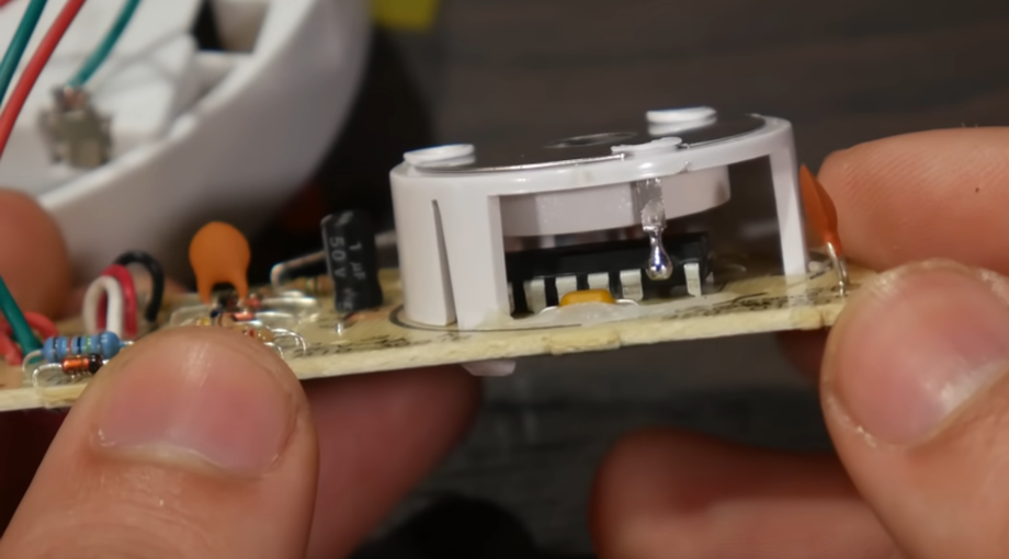
Bent IC Pin in Production
 erco
Posts: 20,263
A clever but questionable shortcut in the assembly of the smoke detector at 5:23 in the video below. One pin on the DIP IC was bent 180 degrees to contact the sensor above. I have broken pins bending less than that. I wouldn't recommend that for this life-critical application. What did they save, one piece of wire costing 1/100 of a penny?


Comments
1/100 of a penny and one less solder point.
If you include it in detail within the build instructions, most board houses will make it however you want.
I'm pretty sure there are legitimate reasons to bend a pin on a DIP package like this. I was reading the datasheet on an op amp commonly used in pH meters and the practice of bending one of the pins was suggested. Apparently if the surface of a PCB is anything but super clean, the PCB surface can conduct enough electricity to interfere with the operation of circuit.
The datasheet included all sorts of other warnings like never touching the chip.
If anyone is interested to know which datasheet this was, I'll try to find it. I'm pretty sure it is referenced in the book Scientific Sensors for the Evil Genius. I don't recommend the book but it did contain some interesting information. It became obvious from reading some of the datasheets referenced in the book that the author had never actually build all the circuits described.
@"Duane Degn" I suggest you look for a copy of the third edition of the Robot book that Gordon wrote originally. It has as his co-author one Myke Predeko. Now I definitely believe that Gordon certainly did build all of the robot systems designed in the book, and even had fun doing so. As for that guy not doing that, I'm keeping an open mind.
Now I've actually seen a board where something was soldered to the chips involved that was added into production. Once on a board originally aimed for running a single keysystem (office telephone) in a box of matched cards, and then yesterday whilst working with a group of fellow computer people at the location for the VCF East events, the VCF (Vintage Computer Federation) is a big group encompassing several museums. One closest to me is the one based at Infoage in Wall Township NJ. Anyway this was a on Grid Systems mainboard, the fellow was trying to clean crud out of it, and showed me the thing, I stated that there was a good reason to do that, but the reason avoided me.
Mascots around but not involved in drafting of message.
Ionization smoke detectors have a very high impedance, or to put it another way, the electrical current produced by the radioactive decay is less than 1 nA. Circuit operation cannot tolerate extraneous currents, thus, the pin has to be isolated from the circuit board. It is easy in production to bend up the pin to make contact with the sense electrode inside the detection chamber. The two pins of the IC on either side of the sensing pin are guard pins, that is, the sense pin goes into an x1 gain buffer amplifier and the output of the amplifier is applied to those two neighboring pins. No current flows when voltages are equal. Most smoke detector chips don't measure the ionization current directly, instead they measure the electrical field within the chamber, which drops when smoke is detected. But same thing, very high impedance, like a pH electrode.
The video explains well how ionization detectors are best at detecting flaming fires that produce great quantities of sub-micron particles, whereas photoelectric detectors focus on smoldering fires that produce literally a thicker smoke. You used to be able to purchase dual mode detectors, ionization plus photoelectric. Back in the 2002 time frame, I worked on a project to monitor smoke levels in third world homes where heating and cooking used biomass fuels. It leveraged mass produced technology of dual mode smoke detectors, hacked to acquire the analog signals into a BASIC Stamp for computation of smoke levels into the two basic size categories.
Man, how you cats deliver solid info in record time! I thought it was just a halfass cost-cutting measure and I done been royally schooled!
TYVM!