

More P2 Eval/Audio questions
 cfox
Posts: 16
cfox
Posts: 16
I'm very interested in audio programming for the P2. Specifically, I'd like to build a synthesizer, including a sampler & realtime effects processor.
To start this process, I found the "headphones.spin2" file in the Propeller Tool's Examples folder, and this seems like a perfect place to start. It plays a single frequency note through each speaker, using very little code, so it's a great learning platform.
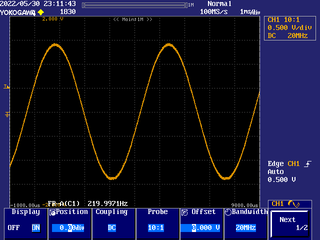
So I edited the file and set the note frequency to 30 Hz and the volume to $7FF. It played a nice 30Hz note, but it sounded like there's some background hissing, so I hooked up my oscilloscope to see what the wave actually looked like.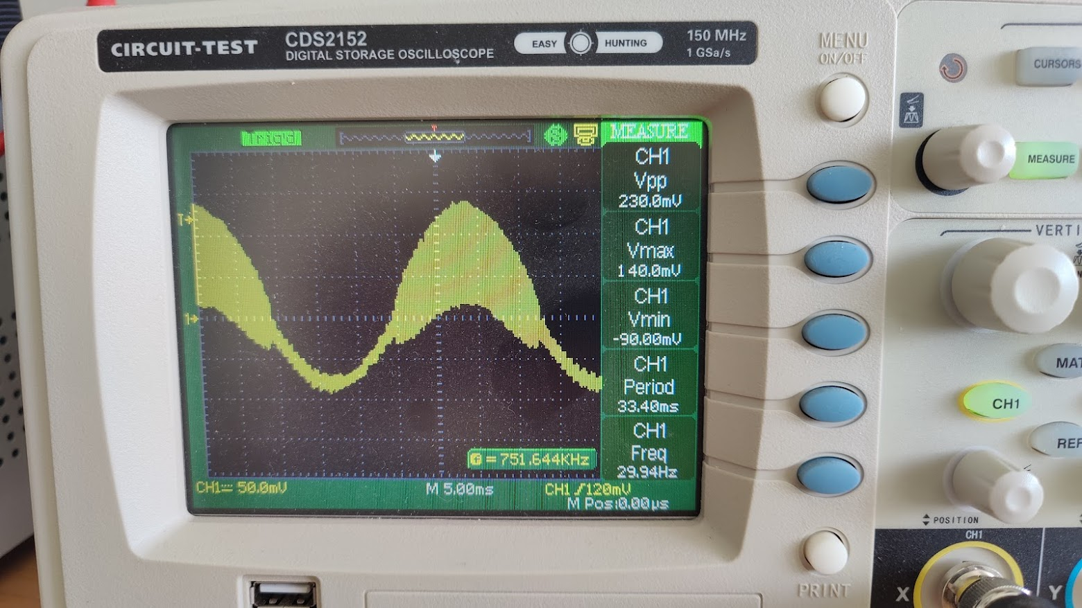
I thought this was rather odd - Sure, it's 30Hz, but it seems to be built of a higher frequency carrier wave, thats "thicker" at the top and thinner at the bottom. This seems very strange. When I zoomed in on that, I saw: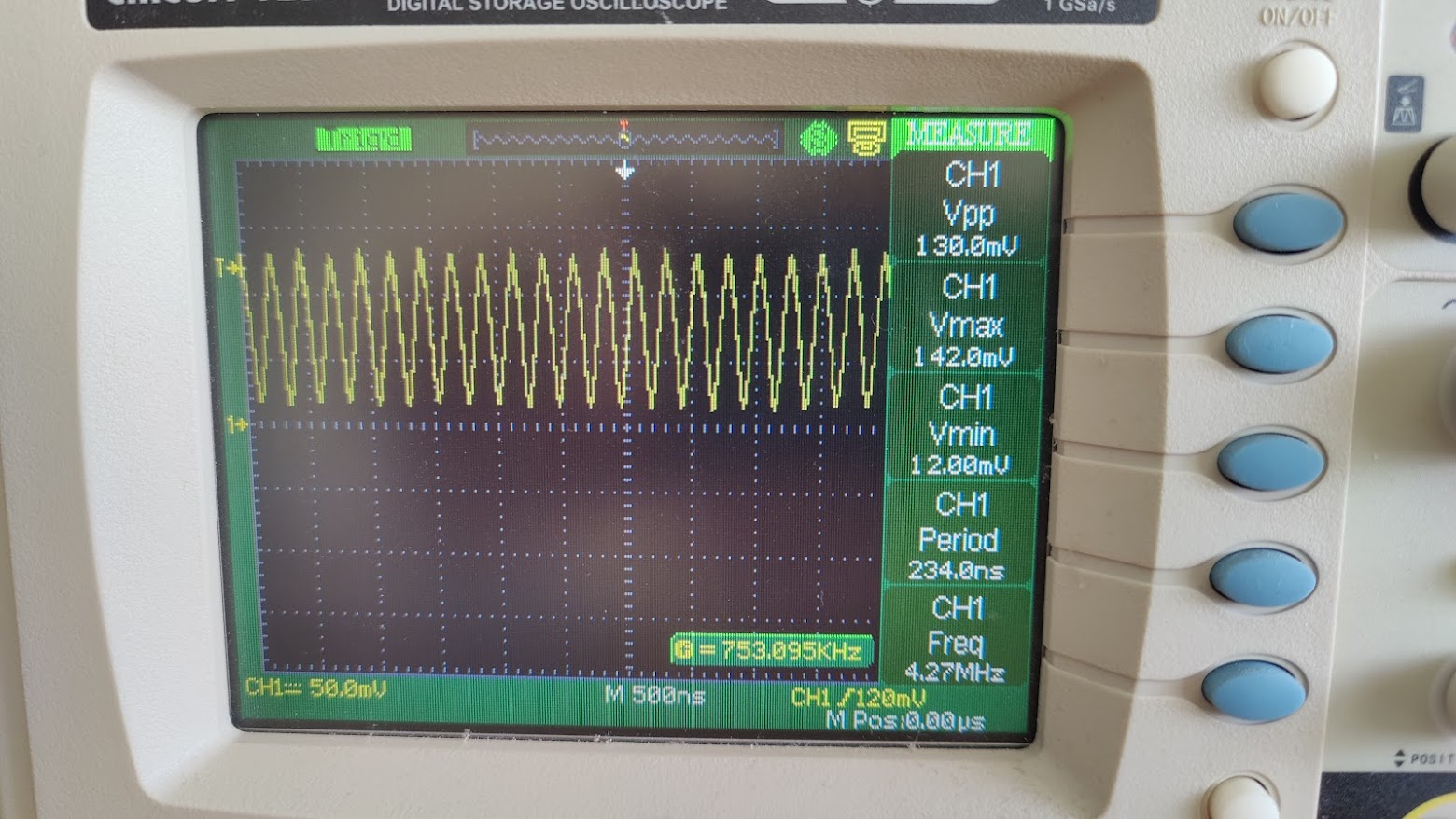
I'm a n00b regarding electronics & oscilloscope usage, so I may have my scope set up incorrectly, but this seems odd. It also seems odd that the wave isn't balanced from top to bottom, from the first image you see that it goes to +140mV but only -90mV. Why the imbalance? And is the carrier oscillation ringing in the circuit, or is it part of the ADC output?
The probe was connected to the left headphone pin on the AV board, not the raw output of the P2 chip, so it is after the capacitor.
I also have some questions about the headphones.spin2 program.
- It uses setse1 & waitse1, but I can't find a clear doc explaining what these instructions actually do in this case. I find mention of the commands, but not enough info to understand what
setse1 #%001<<6+leftis actually doing, or whatwaitse1is actually waiting for. - The f1 & f2 vars are initialized like this:
f1 long round(freq1 * 65536.0 * 65536.0 *256.0 /float(clkfreq_)). It's been a while since I did any fixed point math, but am I correct in assuming this is dividing a circle into 256 elements and converting it to FXP for the cordic rotation calc? - Is it possible to get high quality, low noise audio output from the P2 ADC pins? Do I need to add something to achieve this, like larger capacitors?
- The bottom of the file mentions PWM dither. Is this using PWM? Is that how DAC is accomplished? Is that the carrier frequency we're seeing here?
Comments
I think your scope may be capturing some sort of external interference (power supply?). The PWM carrier would be ~1MHz for the example and way lower in level. Still, it seems to be way above 22kHz so you wouldn't hear it, either way.
The smallest useful sample for audio output is probably the SN76489 emulator object, so check that out if you want: https://forums.parallax.com/discussion/173354/snecog-for-p2
I'm quite sure I'm not picking up external interference. When I disconnect the probe, the signal line goes almost perfectly flat. Interestingly, when I reset the P2 board with the probe still connected to the headphone pin, there is a signal there, and when I zoom in I see that it's a sine wave at 3.5MHz, from 30mV to -30mV, and very stable. This is the default boot-up state - I don't have anything loaded into flash or RAM. Is this to be expected?
Regarding the SE instructions -- thanks for the info, is there a doc somewhere where I can read up on these instructions & states in more detail? The headphone program only sets the value once - the wait is done in the loop, presumably this is how the samples are timed. How else would you do it?
Regarding DAC dithering -- 8 bits is terrible for quality sound reproduction. 16 bits is CD quality, though it sounds like it's a tradeoff. How do you dither two DAC values to one channel? I thought each DAC was associated with a pin? With DAC dithering, can we get 16 bit results, or is there going to be some aliasing, like the nyquist whistle? Is there a doc somewhere that discusses DAC programming?
I'll check out that emulator project.
Yes, you will get some background noise if you're probing the output of an amplifier that isn't being actively driven.
You could just check the pin state manually using testp. That's what I usually do.
It works like this: You write, say, $AA40 to the DAC. This will cause the DAC to alternate between outputting $AA and $AB at a 25% ratio (which filters down to the value exactly 25% of the way between $AA and $AB).
An interesting project that was done with the P1:
https://forums.parallax.com/discussion/101493/project-openstomp-tm-coyote-1-guitar-effects-pedal/p1
Most pics are gone on the forum posts, but here is the old website from the wayback machine:
https://web.archive.org/web/20081225055857/http://www.openstomp.com/
Update: The weird, shaggy sine wave I had at the start of this article was with my oscilloscope connected to one of the headphone pins AFTER the headphone amplifier of the A/V demo board.
I took the A/V board off and connected my scope to the CPU pin directly, and this is what it looks like there:
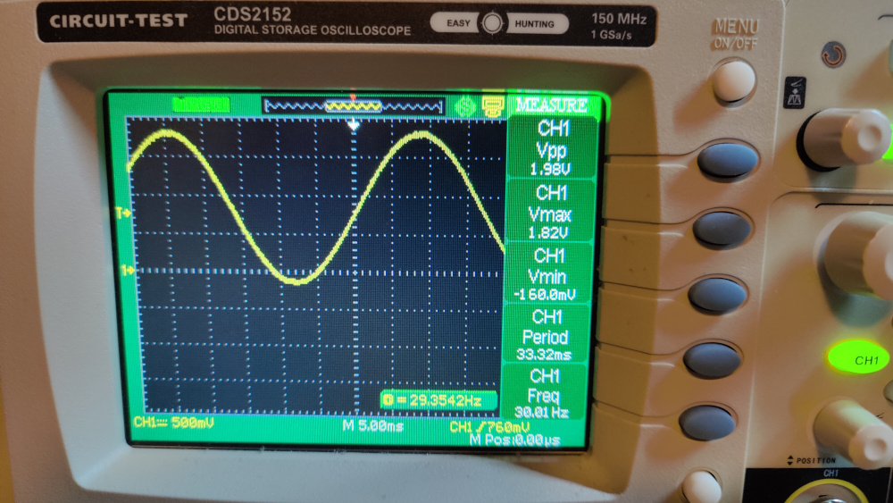
So the output of the DAC is a nice smooth sine - that is a huge relief. When I saw the original crazy output, I thought I'd be facing massive noise or something in the system.
It does raise the question though - why is the amplifier chip adding such crazy noise to the signal?
You've still got an offset in the clean sine wave too. That program uses output drive of 0.0 Volt to 2.0 Volt but the trace indicates roughly -0.2 to 1.8 Volts ...
Program: "headphones.spin2", Volume $7fff, Tone 220.0 Hz, Prop2 pin P31: (note the slight clipping flat at the tops)
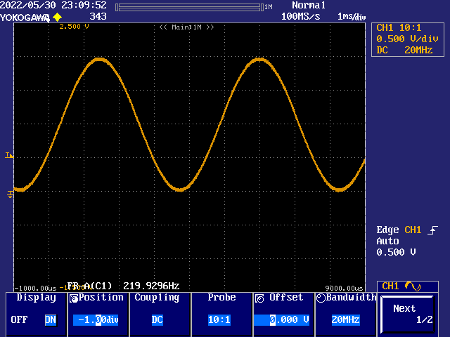
Program: "headphones.spin2", Volume $7fff, Tone 220.0 Hz, A/V accessory: (note the inverted slight clipping flat at the bottoms)
Huh - your second image is with the A/V accessory? I wonder why yours is so clean and mine is SO noisy.... Actually, nevermind, I just discovered the answer to that. I was reading the pin, but I also had headphones connected, and they must have added all that noise - back EMF or something maybe? Anyway when I unplugged the headphones, suddenly the AV board gives me a nice clean sine as well.
As for my values being from -0.120V to 1.8V instead of 0..2V, any idea why this might be? It's a 64000 Rev C P2 eval board. When I look at the AV values, it now goes from -1.42V to +1.34V. Much better, but still a little off.
What's your scope show with probe tip shorted to probe shield? I'm thinking it'll show something like a -0.15 V offset.
Ok, I'm an electronics/oscilloscope newb (been in software all my life). I know what a probe tip is - what's a probe shield?
probe shield = ground of the probe (shield against hum)
You short the probe to calibrate 0 volt on the screen.
The alligator clip is connected to the cable shield which, in turn, is the scope's ground - By which all its measurements are referenced. No ground reference to the device under test, then no accuracy of signal.
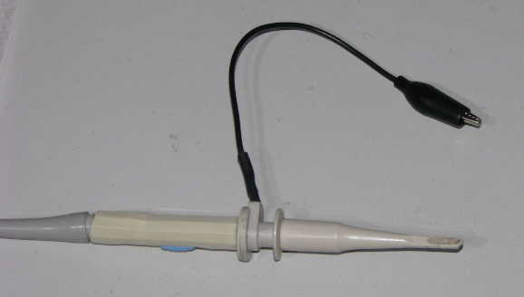
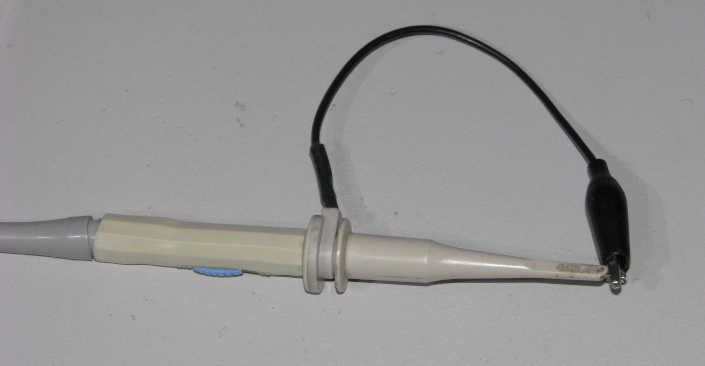
Here it's shorted to the probe tip:
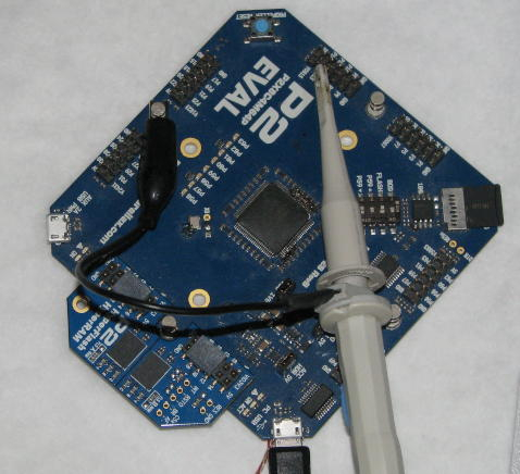
And here, in normal used, ground/shield is clipped to one of the four ground studs of a Prop2 Eval Board (With the probe tip attached to P15 of the second accessory header):
Ok, in retrospect that was a silly question. Thanks for clarifying. Anyway - when I do this, it shows a flat line just below the center line, and the measurements on the side read VMax: -140 mV, VMin: -200 mV. This is an older scope, and I guess I need to tune it or compensate it or something. I'll dig out the manual and see what I can find.
Offset known now at least.
Silly question: cant you fix this using the up/down "Position" knob?
The original problem might have been that your headphones were too low impedance and the amp couldn't drive them, so it oscillated trying to. I have a pair of 34-ohm headphones that sound fantastic.
We are making a board to drive headphones, directly, using 4 ganged 124-ohm DACs per channel, in order to get the impedance down to 31 ohms. This way, we get rid of the distortion that an amp would introduce. We will use a 2.2uF film cap for coupling the treble/mid and a 470uF electrolytic polymer cap to couple the mid/bass.
The best DAC mode to use for audio is the PWM 16-bit mode. You need to have an update rate that is a multiple of 256, though.
Here are the headphones I bought a while back:
https://www.amazon.com/Bowers-Wilkins-P3-S2-Headphones/dp/B01KLS5RX0/ref=sr_1_1?keywords=bowers+wilkins+p3&m=A1BUWB3J6B4OO6&qid=1654042958&s=merchant-items&sr=1-1
My first thought was that the amplifier is using some kind of class D topology, and then you would expect a high frequency PWM signal on the output; But I looked up the amplifier, and it turns out that it's a class AB after all, and the outputs should be quite smooth. Strange!
@Chip
An audio amplifier should be a lot lower impedance than the speaker it drives in order to get good results.
Having impedance matching between an audio amplifier and a speaker will result in low efficiency (50%), slow transient response (slow bass), resonance at speaker Fs (because the amplifier can’t dampen it)
It's the opposite of what any analog signal theory teaches you. The reason is that it's not a voltage signal, it's a power signal! Hi-Fi amplifier manuals usually has got a technical section where they boldly brags about how high the damping factor is. A reasonable good amplifier has got at least >100 and your proposed solution would give 34 / 31 = ~1.09.
I wrote an audio driver which works like Amiga's Paula chip. You give it a pointer to a sample and a period to set the frequency and it plays on its own, up to 32 channels. Then I started several synth experiments, trying to add an envelope, etc...
https://github.com/pik33/P2-retromachine/tree/main/Propeller/Softsynth (initial stage, experimental!!! needs PSRAM)
About these DACs:
They are very high quality, low noise DACs with SNR (accoustic) above 100 dB (tested using an 200W amplifier set to the full power, an ear and a 3-bit "sine wave" where quantization noise can be easily heared (at about -96 dB) and compared to the "silence" noise level. When using a proper noise shaping (as in the P1 driver, only instead of 16->8 bit, make it 24->16), 110 dB SNR is available here (Eval)
But then, in reality, these are fast 8-bit DACs, extended to 16 bit using either noise or PWM. This 110 dB is available in the PWM mode. You will got a noise at clk/256, about 1..1.4 MHz, at about -48 dB, but this is way abowe accoustic band and it can be filtered out if needed. The only problem with the mode is: you have to use CLK/256. Or 512, or 768... Or switch to the noise mode.
To listen and understand the noise dithering mode, you can use the same equipment: the power amplifier. Set the volume to the max and use 1 Hz, low volume sine wave. You can not hear this 1 Hz, but then you can hear this noise. It changes its intensity when the sample value changes in the very interesting pattern. Theoretical SNR in this mode is about 84 dB, so this is not a top hi-fi but it is still good for things like a SID emulator or even a synthesizer, where technical problems like this can make it actually sound better, and not too "sterile".
I tried to use one pair of DACs (stereo) to drive a 32 Ohm headphones: it works, but not as good as it can with a proper headphone amplifier. It will make the sound better, reducing this:
I bought several kits to solder, they are rather cheap and one of them uses 6 (!) transistors at its output stage to make the output impedance way lower than 1 Ohm.