

P2 EDGE slot confusion
 knivd
Posts: 104
knivd
Posts: 104
I am planning to integrate the P2 EDGE module into a complete project and currently working on the component definitions for Altium. According to the slot manufacturer, pin 1 should be on the bottom right corner of the R/A slot looking from top. But on Parallax's edge breadboard (which has a straight slot) the pinout is inverted and pin 1 comes on the lefthand side of the connector. It can't be either way because of the staggering pattern of the pins.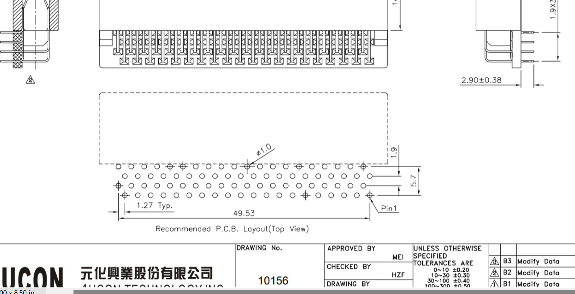
I have built my component according to the pinout of the slot manufacturer, which according to my calculations should have the P2 EDGE module going into it with the P2 chip facing up.

Am I right to assume that the slot pinout was intentionally inverted on the edge breadboard so the module can face the breadboard?
Thanks
Comments
@knivd
I wonder if you would share your source for the edge connector, please?
It is the one Parallax sells:
https://www.parallax.com/product/80-pin-edge-connector-socket-right-angle/
Sorry you had this confusion, and thanks for posting about it.
This is the pinout I have for the right-angle and vertical edge sockets. They seem to match what you have drawn.
I'm wondering if there's an old resource "out there" somewhere... could you share a link to the file you referred to? I'd like to go check it at once and get the confusion resolved.
Oh yeah, that's probably it! The module does face the breadboard.
I'd call that rotated, or turned over. Inverted would be mirrored to the other side of the board - pin 1 would swap sides but not ends, which would be bad.
But, yes, Edge Board probably should be component side up (facing away from the motherboard) when using the R/A edge connector. Otherwise components will be smacking each other in the sandwich. 3.5 mm total space in the sandwich. Probably best to also subtract some clearance from that so not knocking the components. And allows air flow too.
I think inversion is actually the more appropriate term. It it was rorated at 180 degrees the pin pattern would have been the same, but in this case it is the opposite. I suggest take a look at the board and compare to understand what I mean. It is not a problem of any sort if it is known, I just wanted to make sure I am doing it right with the component definition
If you're using a standard library footprint from your PCB tools, rather than Parallax's supplied one, then check its numbering order carefully. It'll likely be the common edge pinout, of interleaved sides - which matches ribbon cabling. Parallax decided to use an alternate circular numbering instead, like how ICs are numbered. This then requires you to completely remap the pins to suit the library footprint.
Here's the PCB top view of the P2 Edge Breadboard #64020 : https://www.parallax.com/product/p2-edge-module-breadboard/
To me it looks like the numbering matches what you have created? (Apologies if I continue to misunderstand something).
If you have a link or file to share that is different then please share and we can gladly investigate. Definitely don't want incorrect info "out there".
To explain what you should see:
Thank you! That clears all my concerns