

Air Quality Monitor (CO2, Temp, RH, Pressure, and now, PARTICULATES) ***Drivers attached***
 Phil Pilgrim (PhiPi)
Posts: 23,514
Phil Pilgrim (PhiPi)
Posts: 23,514
For the past few years, I've been engaged with CO2 sensors of one sort or another. I recently tried the Sensirion SCD30 and came away impressed by it. So I decided to make a small desktop air quality monitor. It uses the Sensirion module, along with an AdaFruit ST7735 color TFT breakout board, and a Propeller FLiP module.
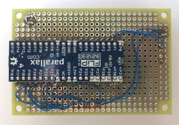
I hand wired the unit on a 2" x 3" Vector board. The FLiP is mounted on the rear side using reverse receptacle strips. I did this both to reduce the overall thickness of the assembly and also so that the the pins from all three modules would come through on the same side so I could wire it. Here's my sloppy wiring work:
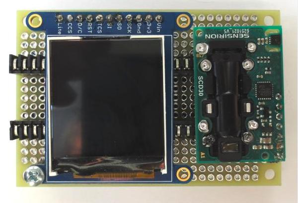
On the front side, the display and sensor are socketed in receptacle strips:
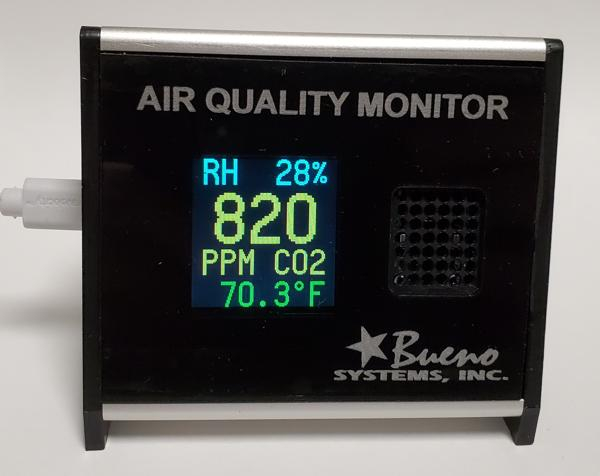
The software includes my revamped ST7735 driver that uses the Propeller font in various sizes. You can see the results here:
The temperature sensor in the SCD30 is subject to the unit's self heating and always registers high. There a way to correct this in the unit's EEPROM, but I decided not to, since I want the unit's actual temperature to correct the CO2 readings for the temperature of its air cavity -- not the ambient temperature. As a consequence, I'll be adding a One-Wire temperature sensor to my assembly to measure ambient temperature.
I actually made two of these and set them next to each other to see if their readings agreed. They did, tracking each other up and down as conditions changed.
I won't be hand-wiring another, though. Even though only 12 wires were necessary, thanks to the FLiP having all the complicated stuff on board, I don't enjoy the process. I will be designing a PCB for it, though, and may even offer it for sale if there's enough interest.
Attached are Spin (P1) drivers for the Sensirion SCD30 and SCD41.
-Phil

Comments
Very nice.
I got the 1-Wire temp sensors today (DS18B20) and wired one into one of the units. It didn't help much, as it also needed correction for the internal enclosure heating. So I opted not to use the 1-Wire sensor and, instead, to make the temperature correction for the SCD30's temperature a constant in the program. That way, I can still use the SCD30's internal temperature to correct the CO2 reading and still display a corrected temperature that fairly well follows the external ambient temperature.
-Phil
There is the new kid on the Sensirion block too, SCD41, which uses the photoacoustic principle rather than NDIR.. It's only 10mm square by 6.5mm high, but apparently competitive in accuracy and stability. I'm curious to try that.
My current go to is the EE894, which is dual wavelength NDIR like the SCD30. It needs 5V power though, a disadvantage with the Prop running on a LiPo cell. I've had to provide a boost supply.
Thanks, Tracy! The SCD40 and SCD41 both look interesting for a volume commercial app, and their prices look good; but the soldering requirements are a bit unapproachable for hobbyist use.
The EE494 and EE495 are both more approachable for soldering and have a built-in baro sensor -- a big plus. They're not sold through distribution, though, and I wasn't able to connect with someone in the company about pricing. Do you know what these run in small quantities?
Thanks,
-Phil
Mouser has the SEK-SCD41 evaluation kit for $56, which is less than the cost of the SCD30. Easy to connect. Granted, the SMT version would be hard to hand solder, a pity, because most of the pins are do-not-connect.
The EE894 came to $116 each in 2019 directly from the Chicago branch of the company. Higher cost than the SCD30. So I'm interested in your experience. The baro is a plus, but probably not that much of a big deal. I see that the Sensirion command set includes an altitude correction. The thing that gets me about all of these is the self-calibration algorithm, which depends on frequent exposure to 400ppm CO2. That is a stretch in many or most locations.
The E+E Elektronik Corporation
333 E. State Parkway |Schaumburg, IL 60173 | USA
Main Office: 847-490-0520
Direct: 847-755-5589
Cell: 847-217-7507
aspore@epluse.com. <-- contact Adam Spore
www.epluse.com
Good to know. Thanks! I'll check it out and include pads for it in my PCB layout.
I always disable auto-calibration in the 20% COZIR units incorporated into one of my products and in the SCD30. It's hard to imagine a situation where auto-calibration would be useful, except perhaps in an air plenum.
I've found the SCD30 to be extremely reliable and consistent. The two AQ monitors I built, placed side-to-side, tracked each other almost perfectly. The temp sensor does suffer from self-heating, but I see that as a plus, since you really want to know the temperature of its air chamber to apply a correction to the CO2 PPMs. For ambient temperature, I just have a constant in my program for correction, although I'm not sure a simple additive constant is entirely adequate. Plus it overcorrects the ambient temp as the SCD30 is warming up.
-Phil
I've completed the design for the PCB:
It will accommodate either the SCD30 or SEK-SCD41, along with a FLiP module (mounted on the rear, and an ST7735 TFT display. There are also three 3-pin accessory headers available on the left side for ... whatever. Power is through the USB connector only.
BTW, the yellow text doesn't get printed on the board; it's only for my reference while doing the layout.
-Phil
That looks great Phil.
I'm curious about the SCD30 power profile. I attach data from the EE894. It fires a visible red lamp that draws a peak current over 300mA, but the average is 3.5mA when sampled at 15 second intervals.
Tracy, here's a scope trace for the voltage measured across a 10-ohm resistor in the SCD30's ground lead. I had the sampling interval set at 2 seconds. So divide the screen voltages by 10 to get the current:
BTW, the IR source in this module appears to be incandescent. The glow is visible through a little window at the base of the sensor. That seems consistent with the current dropping somewhat as the source warms up (i.e. its resistance rising).
-Phil
I've made a couple mods to the PCB:
I realized that the pads on the left could also be used to accommodate a push-button switch. This might be used for switching between °F and °C, for example. Or for switching between text and graphical history modes. So I added a couple pull-ups: R1 for a vertical switch; R2, for a horizontal switch.
Here's an example datasheet for the switches:
https://sten-eswitch-13110800-production.s3.amazonaws.com/system/asset/product_line/data_sheet/29/800.pdf
I also corrected a routing error for SCL and SDA on the SCD41. I had them switched.
-Phil
When/if you get to the point of selling these I’d like to purchase a couple (thanks for your response in the CO2 Clock thread).
Paul
Thanks, Paul, will do. Things I need to change:
And one caveat about plugging in the FLiP from the back side of the board: if you have room, install a standard socket on the back side, rather than through-board socket on the front side. The FLiP's legs aren't quite long enough, without modification, to make good contact with the latter.
-Phil
I finally got around to cleaning up my drivers for the Sensirion SCD30 and SCD41 CO2 sensors. They're attached to the top post in this thread.
-Phil
I've posted a wrapper object in this thread's first post that supports both the SCD30 and SCD41. When started, it checks to see which unit is on the I2C bus, then uses that unit's object for calls going forward. It's not very elegant, but it works. The user still needs to be aware of the subtle differences between the two units, especially as they pertain to each unit's use of internal EEPROM.
-Phil
I've finally had time to expand on the original CO2 monitor PCB. Here's the new layout:
The board is sized to slide into one of my extrusions -- this time without requiring a carrier board. Added are:
I've provided for through-hole parts where I could and SMD parts where I had to. The resistor arrays are duplicated: through-hole and SMD -- the latter for commercial assembly. (The SMD parts are really hard to solder by hand.)
I'll be building a number of these for my own use: renting to local restaurants and other business establishments and providing the data analysis -- a potentially lucrative business. I also plan to make the bare boards available to anyone who wants them to assemble themselves.
More to come ...
-Phil
Phil,
Thank you so much for sharing your work.
I have been meaning to build an air sensor monitor for some time now, and I will follow your project.
I have one of these in my office and it's really fun to watch, especially with the colorful display. Here's how the button changes the time continuum display:
Ken Gracey
Thanks for that video, Ken!
I've made one last change to the board, before sending it off for prototyping:
I added a micro USB socket as an alternate power source. This could come in handy to power the board from a portable charger without involving the USB data connection.
-Phil
The boards arrived, and I've assembled one of them. First light!
I've yet to add coding for the barometric sensor and to write code for the date/time chip. I also need to modify the housing, since the display has moved up from its previous position.
The board design itself needs another round of mods:
More to come!
-Phil
But, D'OH! RTFM, Phil!
At least that's an easy fix, both in the new board redo and retroactively by hand-wiring a fix. Just hope it works. Fortunately, the chip does not drive its outputs high (open-drain outputs only), and its inputs respond to 3.3V logic levels (2.2V input threshold).
And I couldn't figure out why the MS5607 was giving air pressure values that were twice what I expected -- until I rechecked the DigiKey packing slip. Somehow I had ordered MS5611s. At least the driver accommodates those, too, and I was able to get correct values after switching to the '5611 code in the '5607 driver.
-Phil
Got the clock running on 5V, and it keeps time with the power off, due to the CR2032 backup battery. Interestingly, the oscillator in backup mode did not start to run until the chip had been properly powered up the first time.
The battery is not in a location where it could be changed easily. It requires removing the PCB from the housing. So I was concerned about how long the battery will last. An Energizer CR2032 is rated to 235 mAh down to 2V, which is the minimum VBAT for the DS1307. The chip draws <500nA from it. I calculate that the battery will continue to power the chip for more than 50 years, all else being a non-issue. Of course, there'll be leakage current across the PCB, too, which may diminish its lifetime, some. And there is self-discharge, which is rated at 1%/yr. After 35 years, its voltage will still be above 2V. Anyway, having to replace it is not an issue -- for me, at least!")
-Phil
Since that "feature" is not clearly stated at DS1307's datasheet, perhaps it was a "someway unexpected consequence" from the initial testings, when VCC-pin was fed with 3.3V.
Quoted from page 8, under CLOCK AND CALENDAR" (datasheet REV: 3/15):
"Values that correspond to the day of week are user-defined but must be sequential (i.e., if 1 equals Sunday, then 2 equals Monday, and so on.) Illogical time and date entries result in undefined operation. Bit 7 of Register 0 is the clock halt (CH) bit. When this bit is set to 1, the oscillator is disabled. When cleared to 0, the oscillator is enabled. On first application of power to the device the time and date registers are typically reset to 01/01/00 01 00:00:00 (MM/DD/YY DOW HH:MM:SS). The CH bit in the seconds register will be set to a 1. The clock can be halted whenever the timekeeping functions are not required, which minimizes current (IBATDR)."
Also from Maxim line, DS3231-datasheet clearly states that behaviour as an "expected feature" (under Power Control, page 10 of document 19-5170; Rev 10; 3/15).
"To preserve the battery, the first time VBAT is applied to the device, the oscillator will not start up until VCC exceeds VPF, or until a valid I2C address is written to the part. Typical oscillator startup time is less than one second. Approximately 2 seconds after VCC is applied, or a valid I2C address is written, the device makes a temperature measurement and applies the calculated correction to the oscillator. Once the oscillator is running, it continues to run as long as a valid power source is available (VCC or VBAT), and the device continues to measure the temperature and correct the oscillator frequency every 64 seconds. On the first application of power (VCC) or when a valid I2C address is written to the part (VBAT), the time and date registers are reset to 01/01/00 01 00:00:00 (DD/MM/YY DOW HH:MM:SS)."
I've used the DS1307 in my BASIC Stamp loggers (OWL2pe) for almost 20 years, with a Renata CR1220FH cell soldered to the circuit board. That is 48mAh. I've gotten quite a few of those back that have been away for 15 years, as projects wind down or upgrade (!?) to Propeller. Most of them come back with that cell still active, voltage >2.7V. True, the backup cell is not drawn upon when the logger has a primary source of power, but many of these loggers had been unpowered for a long time after being pulled.
I've used the same cell on my Prop loggers to back up an ISL12020 RTC, but that is currently unobtainium, so I'm currently reworking with the MCP79410.
Guess I could've saved some PCB area.
It's handy to know that the MCP79410 is pin-compatible with the DS1307.
Thanks,
-Phil
I'd have to say "!" without question. Tracy, you've done some amazing stuff wrestling 16-bit unsigned math into submission. But signed 32-bit math makes things so much easier. And the program size limitation of Stamps is greatly expanded with the Prop.
On my immediate horizon is recasting a customer's BS2pe MoBo design to use the FLiP module. It won't be an easy transition, since the BS2pe program uses every trick in the book to make everything fit. But once it's done, clear sailing ahead!
-Phil
I'm very interested in purchasing several boards when available. I've been looking for a way to log RH in my house so this would be perfect!
I've made some further modifications to the PCB before submitting for fab:
With the barometer and RTC, there's more information to display, so I included pads for Adafruit's 128x160 TFT display. (I'm a little miffed at Adafruit for not making an effort to keep the pin-out compatible with their 128x128 display.) Anyway, now one has a choice about which display to use. I also included a connector for Sensirion's SPS30 particulate sensor cable. That sensor obviously won't fit the 3" wide enclosure, but I have wider extrusions that everything will fit in. Finally, per Tracy's observation, I could've changed to a smaller battery for the DS1307, but a bird in the hand ...
-Phil
Two last-minute changes:
I had the wrong connector for the SPS30. Changed the Hirose connector for the correct JST connector. I also added an EEPROM to increase the unit's data capture capacity from two weeks to six weeks. The EEPROM uses the FLiP's I2C bus, with A0 set high instead of low.
The SPS30 module presents a bit of a dilemma. It's capable of both asynchronous serial and I2C communication. I like I2C, since everything can be on the same bus, and a separate cog is not necessary to drive it. But the SPS30 data sheet says this:
"Some considerations should be made about the use of the I2C interface. I2C was originally designed to connect two chips on a PCB. When the sensor is connected to the main PCB via a cable, particular attention must be paid to electromagnetic interference and crosstalk. Use as short as possible (< 10 cm) and/or well shielded connection cables. We recommend using the UART interface instead, whenever possible: it is more robust against electromagnetic interference, especially with long connection cables."
The only cable I could get for it is 10 cm long. Although a 5 cm cable is listed by JST, no one has it in stock. But I'm going to risk it anyway. If I run into trouble, I can always move SCL and SDA to P6 and P7, then bring P4 and P5 down to the SPS30 connector. The other option would be to do that anyway and add two more pull-ups, so that the SPS30 could be on its own I2C bus or, optionally, operated serially. But adding two more pull-ups gets real messy at this stage of the layout.
-Phil
In my experience you can often push I2C quite a distance. In one installation I had three sensors inside a large motor. The data path was nearly 2 meters long and the environment was way beyond electrically “noisy”. It worked fine. We used Belden 8723 cable inside a stainless mesh sleeve (abrasion prevention) and used stiff pull-ups. I was amazed. Nary a problem.
I bet your 10 cm cable works just ducky. 👍
The problem with i2c on long cables usually comes down to crosstalk, and Sensirion made a bad design decision (in perspective) by putting those two signals side by side in the ribbon cable connector, without a power or ground line in between. When sda changes state in between clock edges, capacitance between the wires can couple a short pulse into scl and wreak havoc. When I put other sensors like the Sensirion SHT31 or the SHT15 out on the end of 15 or 20 foot cables, I use cable that has the sda and scl lines diagonally opposite one another, with the power and ground on the intervening diagonal. Or separated in whatever way. You'll probably okay with the 10cm. It can sometimes help to slow down edges on purpose.
I do appreciate that you have separate i2c for the peripherals, apart from the p28/p29 eeprom bus. It would be so annoying if a glitch in an outside i2c peripheral were to brick the whole system. I like to put the RTC on the system bus too, essential core.
I'd suggest you add a connection from Prop p6 to DS1307 pin 7, with a high ohms pullup. The 1 second heartbeat from the RTC can be useful.