

P2Eval <--> TinyFPGA
 Rayman
Posts: 16,460
Rayman
Posts: 16,460
Trying to learn FPGA again and using the P2 Eval board to help.
Tried using some expensive FPGA boards before, but it's just too complex and became overwhelming and just too much work to figure anything out.
This time, using a very simple board, TinyFPGA.
Mentioning it here because using the P2 Eval board to help.
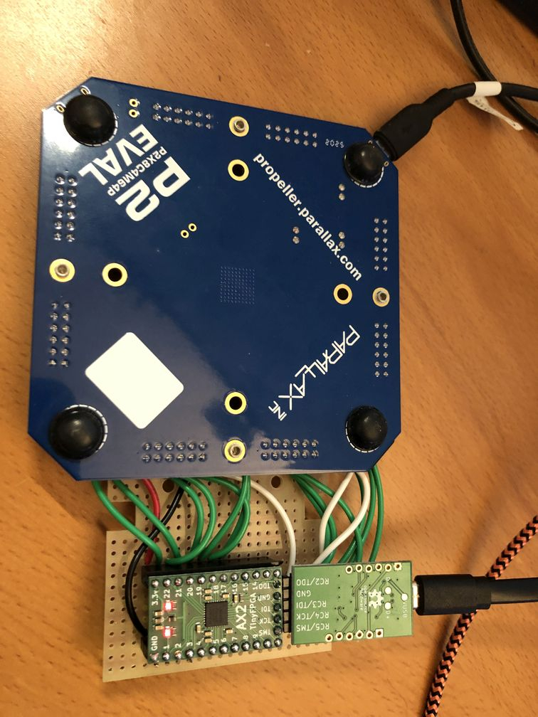
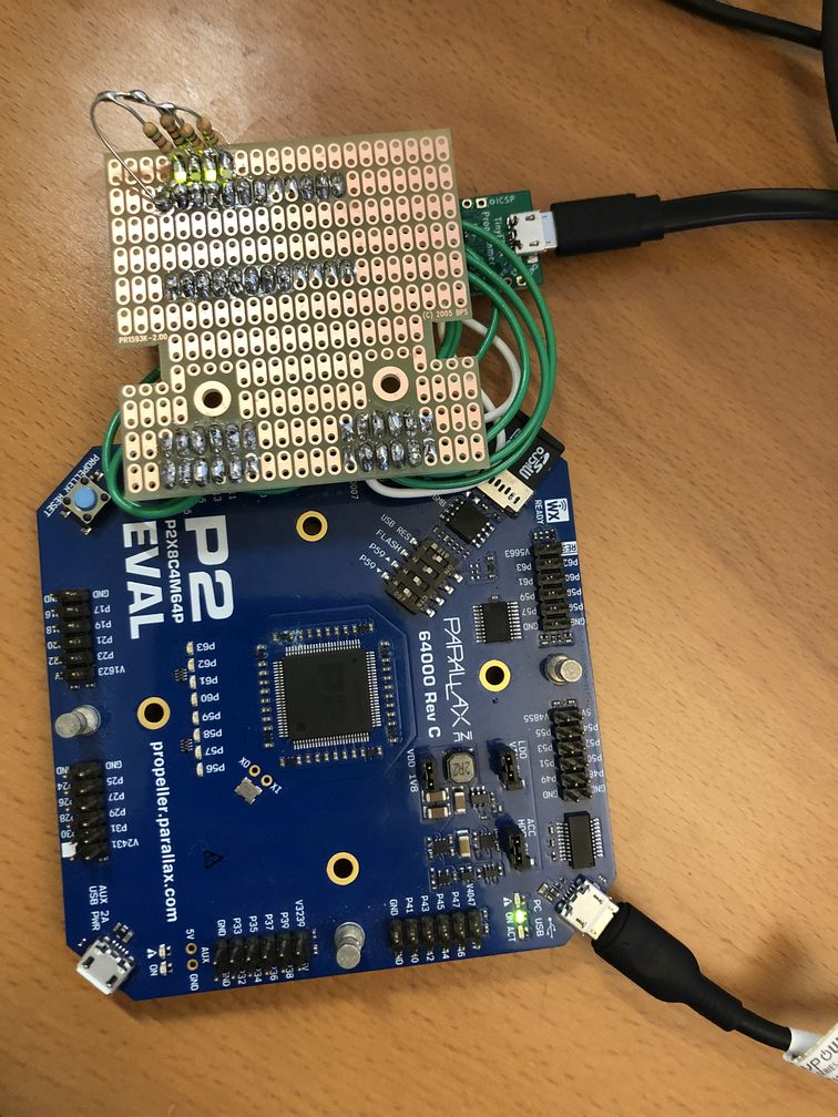
The P2 Eval provides power and a 16-bit interface for I/O with TinyFPGA
Made some notes on TinyFPGA here: http://www.rayslogic.com/TinyFPGA/TinyFPGA.htm
Notes on this interface are going here: http://www.rayslogic.com/TinyFPGA/TinyFPGA_To_P2Eval.htm
756 x 1008 - 133K
756 x 1008 - 174K
Comments
I'm pretty sure we can also program the MachXO2 chip using the P2, but haven't figured out how yet.
BTW: The goal in mind is to create a 4-bit CPU. Starting with a 4-bit ALU. Was thinking about doing it with ancient IC chips, but this is more interesting (and less work).
Seems we have 16 I/O pins that we can easily use.
So, current plan is to use 8 as inputs and 8 as outputs.
Will make a program in FlexC that takes input via serial port and then shows the output.
Could use for automated testing of future designs.
A simple CPU can be simply done in Verilog. Maybe I can find (and then place here) the code I did for my students at the university several years ago. The resulting 8-bit CPU eats up - if I can remember - about 600 (Edit: 379) LEs of Altera Cyclone 4
and there it is.
module simple8(addr,din,dout,rw,md,irq,reset,clk,debug); //(c) 2017.04.15 Piotr Kardasz // pik33@o2.pl // license: GPL 2.0 input wire [7:0] din; // data in output reg [7:0] dout; // data out output reg [7:0] addr; // address output reg rw; // 0 - write; 1 - read output reg md; // 0 - memory, 1- device input wire irq; // irqerrupt, negedge input wire clk; // clock input wire reset; // reset output [7:0] debug; reg [7:0] acc; // accumulator reg [7:0] sp; // program counter reg [7:0] pc; // stack poirqer reg [1:0] flags, iflags; // flags: IZC reg [1:0] irqreq; reg[7:0] arg,opcode; reg[3:0] phase; reg[7:0] ramaddr,ramdatain,ramdataout; assign debug=pc; (* ramstyle = "M9K" *) reg [7:0] ram[256]; // memory for the CPU initial begin acc<=0; sp<=8'hfe; pc<=0; flags<=0; iflags<=0; phase<=0; opcode<=0; rw<=1; $readmemh("ram.hex",ram); end always@(negedge clk) begin if ((rw==0) && (md==0)) ram[ramaddr]<=ramdataout; else ramdatain<=ram[ramaddr]; end always@(posedge clk) begin if (~irq && irqreq==0) irqreq<=1; if (~reset) // standard: reset active low begin acc<=0; sp<=8'hfe; // ff=irqerrupt vector pc<=0; flags<=0; iflags<=0; phase<=0; opcode<=0; rw<=1; end else begin case (phase) 0: // get an opcode begin if (irqreq==1) // interrupt acknowledge begin phase<=10; irqreq<=2; end else begin rw<=1; ramaddr<=pc; md<=0; pc<=pc+1; phase<=1; end end 1: begin opcode<=ramdatain; phase<=2; end 2: // decode address mode begin if (opcode[7:6]==2'b10 ) // imm begin rw<=1; ramaddr<=pc; md<=0; pc=pc+1; phase<=3; end else if (opcode[7:6]==2'b11 ) // abs begin rw<=1; md<=0; ramaddr<=pc; pc=pc+1; phase<=4; end else phase<=6; // acc or imp end 3: begin arg<=ramdatain; phase<=6; end 4: begin ramaddr<=ramdatain; rw<=1; pc<=0; phase<=5; end 5: begin arg<=ramdatain; phase<=6; end 6: // execute the opcode begin case (opcode) 8'h29: // ret begin sp<=sp+1; ramaddr<=sp+1; rw<=1; md<=0; phase<=7; end 8'h2a: // iret begin sp<=sp+1; ramaddr<=sp+1; rw<=1; md<=0; flags<=iflags; phase<=7; irqreq<=0; end 8'h41: // shl a begin flags[0]<=acc[7]; acc<=acc<<1; phase<=0; end 8'h42: // shr a begin flags[0]<=acc[0]; acc<=acc>>1; phase<=0; end 8'h61: // bne a begin if (flags[1]==0) pc<=acc; phase<=0; end 8'h62: // bcs a begin if (flags[0]==1) pc<=acc; phase<=0; end 8'h64: // jmp a begin pc<=acc; phase<=0; end 8'h68: // call a begin ramaddr<=sp; ramdataout<=pc; rw<=0; md<=0; sp<=sp-1; pc<=acc; phase<=0; end 8'h71: // push a begin ramaddr<=sp; ramdataout<=acc; rw<=0; md<=0; sp<=sp-1; phase<=0; end 8'h72: // pop a begin sp<=sp+1; ramaddr<=sp+1; rw<=1; md<=1; phase<=8; end 8'h81, 8'hc1: // adc #, adc abs begin {flags[0],acc}<=acc+arg+flags[0]; flags[1]<=~(&(acc+arg+flags[0])); phase<=0; end 8'h82, 8'hc2: // sbc #, sbc abs begin {flags[0],acc}<=acc-arg-flags[0]; flags[1]<=~(&(acc+arg+flags[0])); phase<=0; end 8'h84, 8'hc4: // and #, and abs begin acc<=acc&arg; flags[1]<=~(&(acc&arg)); phase<=0; end 8'h85, 8'hc5: // or #, or abs begin acc<=acc|arg; flags[1]<=~(&(acc|arg)); phase<=0; end 8'h86, 8'hc6: // xor #, xor abs begin acc<=acc^arg; flags[1]<=~(&(acc^arg)); phase<=0; end 8'h91, 8'hd1: // lda #, lda abs begin acc<=arg; phase<=0; end 8'hd2: // sta abs - sta # is nonsense begin ramaddr<=arg; ramdataout<=acc; rw<=0; md<=0; phase<=0; end 8'h94, 8'hd4: // in #, in abs begin addr<=arg; rw<=1; md<=1; phase<=9; // need to wait for i/o end 8'h95, 8'hd5: // out #, out abs begin addr<=arg; rw<=0; md<=1; dout<=acc; phase<=0; end 8'ha1, 8'he1: // bne #, bne abs begin if (flags[1]==0) pc<=arg; phase<=0; end 8'ha2, 8'he2: // bcs #, bcs abs begin if (flags[0]==1) pc<=arg; phase<=0; end 8'ha4, 8'he4: // jmp #, jmp abs begin pc<=arg; phase<=0; end 8'ha8, 8'he8: // call #, call abs begin ramaddr<=sp; ramdataout<=pc; rw<=0; md<=0; sp<=sp-1; pc<=arg; phase<=0; end default: phase<=0; endcase end 7: // get the pc from RAM begin pc<=ramdatain; phase<=0; end 8: // get the acc from RAM begin acc<=ramdatain; phase<=0; end 9: // get the data from the device begin acc<=din; phase<=0; end 10: // interrupt phase 1 - save flags and return address begin iflags<=flags; ramaddr<=sp; ramdataout<=pc; rw<=0; md<=0; sp<=sp-1; phase<=11; end 11: // interrupt phase 2 - get vector from $FF begin ramaddr<=255; rw<=1; md<=0; phase<=12; end 12: // interrupt phase 3 - get vector from $FF begin pc<=ramdatain; phase<=0; end endcase end end endmodulePiotr, what is the maximum clock frequency ?
I don't remember now. I did this thing for the student's lecture. (I teached basics of FPGA) - but generally this kind of thing works up to 100..200 MHz in Cyclone IV (DE2-115)
The goal was to show students how to make a CPU and peripherals in FPGA, so I also wrote some peripherals (switch input, LED output, 7-segment output) and address decoder, then I connected all of this using Quartus GUI to show the structure of such a system
This CPU has 8-bit (!) memory address space using FPGA's internal memory and separate, 8-bit I/O address space.
Got a 74181 ALU coded up in Verilog.
Going to use P2 to do some automated testing to see if it's right.
Found some C code for 74181 in an old version of Mame: https://github.com/mamedev/historic-mame/blob/master/src/emu/machine/74181.c
Can compare the output of that with FlexProp C to what the fpga is putting out.
The 74181 is actually fairly complex for such an old chip.
And, getting the Verilog to match took a fair amount of time.
I probably made some mistakes somewhere, so this is going to be a big help.
I've got an old VHDL textbook wherein one chapter is entirely replicating an AM2901 (4-bit ALU) in an FPGA. S.
There is the MiSTer project that implements 80/90ies home computers and game consoles using FPGA. Including 68K processors. See eg https://github.com/MiSTer-devel/Minimig-AGA_MiSTer
The P2 was a big help with testing the 74181 in verilog.
Found several bugs.
My carry out is wrong (always 0) when doing logic functions.
I think this is how it should be, but the actual chip doesn't care about M when outputting the carry...
Also, I think there was a bug in the carry out in that Mame code, that I fixed.
Don't know enough about their code to say for sure, but had to change something to match what I think is correct.
This page is very helpful with that: http://www.righto.com/2017/03/inside-vintage-74181-alu-chip-how-it.html