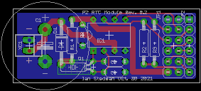
P2 Real-Time Clock (RTC) with Capacitor backup gizmo
 Scroungre
Posts: 161
Anyone want one?
I'm sure Parallax, or at least someone with a Mikro-Clik has already done this, but I wanted to make my own.
Basically, it's designed to use an MCP7940 Real Time Clock (RTC) chip, and uses a 1F (Yes, one Farad(!)) capacitor as backup power. Experiments using the same chip, same cap, and very similar circuitry have shown that it'll keep time for two weeks with power-off, and simulations say it'll last for a month -ish. The cap may be too big.
While you can input a 32.768kHz clock into your P2, it won't do things like thermal correction and trimming like a real RTC chip will. I learned this the hard way - If you want to make a clock, get a real RTC.
At the moment I have a hardware design. It's a schematic and a PCB layout. I have not built any of these things, and I hope to use JonnyMac's I2C drivers (At eight bits width, pace Mr. McPhalen) to communicate with it. I just have to write wrappers about his interface code in order to talk to the chip.
Other details:
Given that the RTC needed only three I/O pins, I stuck on a connector (JP2) - on the wrong end - for the remaining five I/O pins on that port, in case someone wanted an easy way to connect some stray pins. Pin 1 is ground (standard practice).
The cap is in fact too big - It's too wide, and will interfere sideways with other plug-in cards (on a KISS). You can solder in the cap from below (as intended), or from above with spacers, looking like a giant flying saucer, but it's too wide, and will interfere unless you design around it. Thus I threw in another connector (X1), so you can connect an external cap on flying leads. The polarity has flipped to make a right-angle connector suitable.
The cap is in fact too big. The time-constant for fully filling the cap is about ten minutes, so when you first power-up the thing you should potter about with it for awhile, because the cap will take ten minutes to charge.
You could use a smaller-value resistor in the inrush current limit (at the moment, 120ohms) at risk of pulling so much current when the capacitor is cold that it'll make things weird. Not recommended.
As usual, suggestions and hints on how to make it better are welcomed, S.


Comments
Nice. Your board looks handy. I am using the MCP79401 myself but it's very similar to the MCP7940.
It seems to be missing a pull up resistor for the SCL pin. Was this intentional? Pullups are somewhat redundant due to the P2 having the capability to provide them internally with programmable options of 1.5k or 15k but it's nice to have an option of fitting them should someone need finer control of the resistance for their own bus timing purposes. It makes sense to keep the I2C bus pins where you have them on the 8 bit port so this board could be populated on the P56-P63 header of P2 EVAL etc with the I2C bus using P56 and P57. The MFP pin can simply be left disabled in the chip when operating in that case as it already floats high by default in an open drain state (maybe its resistor can be left out - or repurposed for SCL). Breaking out the other unsued pins for further use or probing etc is a good idea although IMO it might make sense to separate them by more than 0.1 inch from the other header pins so the board doesn't get installed incorrectly. Hopefully you might be able to source a physically smaller super cap that fits the width of your board.
Good thoughts.
I was told on another thread that I can trust the P2's pullups. But I could stick in a 3rd. Anyone with experience in I2C on whether I2C on the P2 needs an SCL pullup? I did put one on my AVR boards using this same RTC chip.
I like the MFP pin. I've used it several times on AVR-based boards. As I recall the spec sheet says 'if not used, can be left open'.
I put the connector pins on an 0.1" grid on the vague idea that someone might want to use a three-row header? If you build it wrong, well, it won't work... Also I wanted to keep that end of the board real short, so it won't interfere with anything on the P2 Edge boards. It still might, on some of the really small P2 Edge ones (it's fine on the JonnyMac breadboard). I should check those.
The 1F cap has the wonderful advantage that I happen to have a handful of them.
I'll stick that resistor in somewhere, unless someone tells me not to. S.
If you want to support clock stretching from the device being accessed or to support multi-master capability I believe you would need to use a pull up resistor on the SCL clock signal (either internal to the P2 or external). You won't want to drive clock high from the master in that case, but let it be pulled high with the resistor instead when you float it from the P2.
I think you can trust the P2's internal pullups for I2C, but I know on my own board I did fit some resistors anyway, as I had used this special I2C hotswap pass through chip (where you can power down one side and in theory your I2C bus can continue on the other side) and I wanted to follow its circuit layout.
I figured 1/8W resistors would be fine for the pullups (but NOT R1!) so I easily wedged in another one. If not required, one can always just not install them.
It looks like it'll fit on the smallest of the P2 edge boards that Parallax sells. I've not checked out the other builders. Tidied up a few other bits. The board remains at 0.7" x 1.75", the cap is slightly over 0.8" across.
Dunno when I'll get around to making any. I might sit on it for awhile until I have some more boards that I can put into one order, and save on shipping costs. Maybe I should make some right-handed KISS adapter boards... S.
@Scroungre I’ve made a couple accessory boards for the P2-EVAL, and on the last one I did something you might consider. Instead of using the slide-over-pin connectors that Parallax uses to attach the board to the EVAL, I use long pin socketed headers ala the RPi. The socket on the bottom of the acc board fits the pin headers on the EVAL, and the tail leads protrude thru the acc board about a half an inch. This lets me stack the accessory boards (saves wasting pins!), and the extended leads make it really easy to get a scope probe on for testing. They are also mechanically stout. Just a thought.
Sound interesting. Got a picture of that setup?
@Scroungre You might also like to consider having a second pin pitch inside your existing cap footprint for other cap sizes given you have room there for that. By the looks of the parts in the link below it seems 5mm pitch between leads is also used. These smaller types would fit your board width nicely but only seem to go up to 0.22F which is still probably okay in some applications where power off times are less. You might get days not weeks of backup with these for example.
https://www.rockby.com.au/searchresSql_12.cfm?select=07&subcode=485
Hmm. I looked, and I don't think they could be centered. Note these things need quite large holes (0.050", in my cap's case, and the leads on those look very similar), and so if I tried to put them all on the same vertical line you'd get holes (not just pads!) very close to each other (if not actually overlapping), and I don't think the board house would like that very much.
However, if you just added one hole, and put the 0.22F cap off-center, that would work, but moreover it still wouldn't (by a hair!) overlap the edge of the board!
0.22F would probably be plenty for this application anyhow. I'm thinking more along the lines of 'wall clock that can tolerate a power outage' rather than anything more sophisticated. If your house (or office) power has gone down for two weeks, you have bigger problems than resetting the clocks.
It would also work fine for a clock that got, say, 'turned off at night', or anything like that which would care to know what time it is.
1F is better for something that wants to turn on once a week or so at a specified time, then turn itself off again. Examples of that might be things like automatic offline backups, photographing the growth of a tree, &c.
I'll stick another hole in. S.
And have another picture. There's three pullups now, and note the capacitor rings - the smaller one is supposed to be the 14mm 0.22F from rogloh's link, and yes, it fits. The crude simulation says 0.22F should 'hold and count time' for eight and a half days -ish (I'd not trust that without a LOT of testing). Have fun! S.
PS - Long-pin sockets should work fine. If you're going to do that, be sure the housing of the socket is on the same side as the cap for best vertical clearance.