NTC linearization
 ManAtWork
Posts: 2,296
The cheapest method to measure the temperature of the PCB itself or a nearby heatsink, motor or whatsoever is probably to put an NTC or PTC resistor on it. Together with a normal resistor it makes a voltage divider which can be sampled with an ADC input.
The disadvantage is that the voltage to temperature relation is highly non-linear.
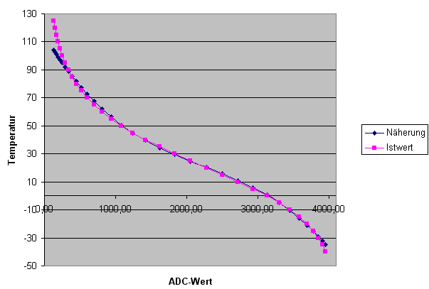
The picture shows the ADC value (12 bit) on the X axis and the corresponding temperature (°C) on the Y axis. The blue curve is the actual value calculated from the nominal resistance/temperature values from the data sheet. The purple curve is a polynomial approximation.
PUB AdcToTemp (a) : t | x
// polynomial approximation, a=12 bit ADC value, t=temperature in 0.1°C units
{
    x:= 1827 - a
    t:= (x * 112) + (294*512)
    x:= x*x / 4096
    t+= (x * 115)
    x:= x*x / 4096
    t+= (x * 382)
    return t / 512
}
The above code is optimized for integer math and should work for 10k NTCs from Guangdong (B=3950) together with a 10k pullup resistor in the range from -25 to +90°C. However, if the NTC type is changed or a different temperature range is required the coefficients have to be re-calculated which is not that easy.
Now that we have floating point math in Spin2 maybe somebody has better formulas where the resistor and B values can be inserted directly?


Comments
There is also this approach, where you use carefully chosen 1 or 2 more resistors, to linearize the voltage transfer.
From here, and additional sine-style correction could be applied if desired.
https://www.mouser.com/pdfdocs/930-187A-Thermometrics-NTC-SensorLinearization-021518-web-4.pdf
Hmm, 32% improvement sounds good, but if you look at the total error it's still something around +/-10°C. So you still need polynomial linearization to get reasonable readings and nothing is saved. It actually makes things worse because with more resistors the coefficients are harder to calculate.