New wheels!
 VonSzarvas
Posts: 3,623
Curious if anyone else has seen these new motor wheels with mountings:
https://www.parallax.com/product/6-5-hub-motors-with-encoders-and-mounting-blocks-bundle/
I'm thinking about a good platform to use for these- we found some aluminum profiles left over in the office from an old CNC machine which might work well as a base.
Very interested to hear if anyone else has plans/ideas. These motors seem wildly powerful, and could make some interesting robotic tasks possible.


Comments
I wonder if this is a good controller for the wheel? It's at a good price right now.
https://www.parallax.com/product/parallax-xrotor-20a-electronic-speed-controller/
Looks interesting, I'm guessing those are hoverboard wheels. Watch out for explosions & runaway accelerations!
I have a hover board and they work ok and are nice to ride but are not good for all types of terrain.
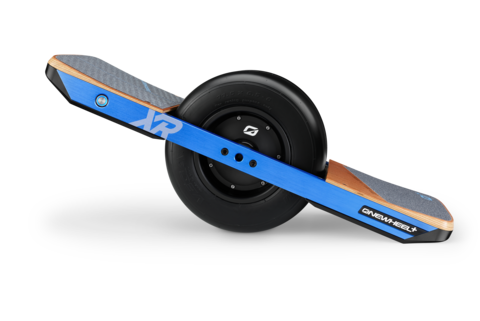
I recently stepped up to the One Wheel. Far more useful than a hover board.

Great engineering. Uses battery tech from electric cars. Blue tooth connect to your phone so you can set ride parameters as well as check charge level and distance traveled along with speed.
Can be used on many different surfaces such as lawns and golf courses.
Rides like a surf board.
Mike
I don't see any answers for what is a good motor driver, or is that still under development?
Jim
Still in development. I wonder if this would work in the mean time:
https://www.parallax.com/product/parallax-xrotor-20a-electronic-speed-controller/
There is a P2 accessory motor controller with part number 64010. If it doesn't appear before, I'll show it at the P2LF week after next.
I know the PCBs arrived, but not sure about all the components to get it through manufacturing. Could be imminent though, with some supply chain luck.
cool
Chip talks about the motor controller in this video:

It's a race !!! ... just kidding. We are finalizing the development of our own BLDC motor controller and hope to have it ironed out by the end of this week or next. The Test bench works and all of the code is valid, but the final PCB has an issue we need to resolve. I did hand solder the PCB, so there might be an issue from that. Time to diagnose this week.
Our board measures 2 x 4.5 inches and we are driving the motor with 48 Volt battery pack and under extreme loads will be briefly pulling 16 Amps. Max speed of our application is 300 RPM
Beau,
Interesting
What micro will you be driving it with, or what is the interface?
"What micro will you be driving it with..." The micro is already on the board and it is a PIC16F15323. (far Left on image) As I said the code works on the bench... I just did something stupid in the translation somewhere. The HUB diameter of my motor is about 15 inches and will just about take my foot off if I try to stop the motor from turning. The motor is RPM driven so that its goal is to maintain a specific RPM and dynamically adjust current to get there if there is any load put on the motor that would otherwise try to slow it down.
Just a brief update and then I will back out and we can return to topic.
I found the problem on the PCB and got the motor up and running today !!! There was a 1uF cap that needed to be a 10uF instead. AND the circuit I had for visual feedback of the HALL sensor status was causing problems with the micro being able to properly read the state. So I removed the LED's and fixed the Caps . Yay !!!
I forgot to mention in that video.... The motor hub weighs about 30 pounds and does NOT have the weight evenly distributed internally, and still the dynamic braking works amazingly well.