

Goertzel example: linear position sensor
 ManAtWork
Posts: 2,369
ManAtWork
Posts: 2,369
I'm experimenting with the Goertzel mode to build a capacitive position sensor. 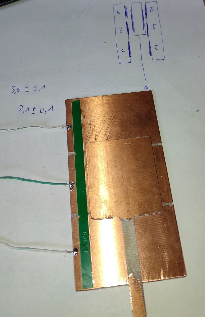
I've taken Chip's example and modified it a bit.
' Goertzel input and display
' original source from Chip's "Goertzel_OUT_and_IN.spin2"
' modified by N. Benezan for capacitive position sensor or LVDT

CON
  _xtlfreq = 25_000_000
  _clkfreq = 180_000_000

VAR dacpins          '[0] dac pins to receive output cos/sin                - read once at start
    adcpin           '[1] adc pin to sense return signal                    - read once at start
    adcmag           '[2] adc magnification 0..4 = 1x, 3x, 10x, 31x, 100x   - read once at start
    frequency        '[3] output frequency                                  - read every loop
    cycles           '[4] number of cycles per loop                         - read every loop
    phase            '[5] 9-bit phase offset                                - read every loop
    power            '[6] measured input power                              - written every loop
    angle            '[7] 32-bit measured angle                             - written every loop
    done             '[8] done flag = 1                                     - written every loop

    buffer[512]

PUB go() | i

  dacpins   := 32 addpins 3
  adcpin    := 38
  adcmag    := 2 ' gain 10x

  frequency := 1000_000 ' 1MHz
  cycles    := 100
  phase     := 0

  coginit(newcog, @goertzel, @dacpins)

  repeat until done ' wait for cog startup
  debug (UHEX_LONG_ARRAY(@buffer, 10)) ' display mirror of LUT in hub
  'repeat

  debug(`scope_xy s 'Goertzel' samples 10 dotsize 20 size 300 range 100_000_000 polar logscale)

  repeat
    waitms(10)
    debug(`s `(power, angle))


' Setup

DAT             org

goertzel

' Make sine and cosine tables in LUT bytes 3,2,1,0
                mov     ptrb, ptra              ' buffer for debugging
                add     ptrb,#9*4
                mov     .z,#$1FF                'make 512-sample sin/cos table in LUT
.sincos         shl     .z,#32-9                'get angle into top 9 bits of z
                qrotate #127,.z                 'rotate (127,0) by z
                shr     .z,#32-9                'restore z
                getqx   .x                      'get x
                getqy   .y                      'get y
                setbyte .x,.y,#1                'sin:cos into x
                setword .x,.x,#1                'sin:cos:-sin:-cos into x
                xor     .x,##$FFFF
                wrlut   .x,.z                   'write into LUT
                wrlong  .x,ptrb++
                djnf    .z,#.sincos             'loop until 512 samples

' configure dac and adc pins

                setq    #3-1                    'read pin data
                rdlong  .dacpins,ptra++

                mov     .x,.adcpin              'get dds d operand
                and     .x,#%111100
                shl     .x,#19-2
                or      .dds_d,.x

                mov     .x,.adcpin              'get dds s operand
                and     .x,#%000011
                decod   .x,.x
                shl     .x,#12
                or      .dds_s,.x

                fle     .adcmag,#4              'enable adc pin
                shl     .adcmag,#15
                add     .adcmode,.adcmag
                wrpin   .adcmode,.adcpin

                cogid   .x                      'enable dac pins
                setnib  .dacmode,.x,#2
                wrpin   .dacmode,.dacpins
                drvl    .dacpins

                mov     .done,#1                'set done flag

' Input Goertzel settings, start measurement, output prior results, loop

.loop           setq    #3-1                    'read input data
                rdlong  .frequency,ptra++

                rdlong  .x,#@clkfreq            'compute NCO frequency
                shl     .x,#1
                qfrac   .frequency,.x
                getqx   .y

                setword .dds_d,.cycles,#0       'set cycles

                sets    .dds_s,.phase           'set phase

                setq    .y                      'issue new Goertzel command with new frequency
                xcont   .dds_d,.dds_s

                getxacc .x                      'get prior Goertzel reading, cos first
                mov     .y,0-0                  '..then sin

                qvector .x,.y                   'convert (x,y) to (power,angle)
                getqx   .power                  'get power
                getqy   .angle                  'get angle

                setq    #3-1                    'write output data
                wrlong  .power,ptra++

                sub     ptra,#6*4               'point ptra back to .frequency

                jmp     #.loop                  'loop

'Data

.adcmode        long    %0000_0000_000_100011_0000000_00_00000_0        'ADC mode
.dacmode        long    %0000_0000_000_10111_00000000_01_00000_0        'DAC mode

.dds_d          long    %1111_1000_0000_0111_0000000000000000           'Goertzel mode
.dds_s          long    %000_000000000                                  ' 512 entry LUT

.dacpins        res     1       'read once at start
.adcpin         res     1
.adcmag         res     1
.frequency      res     1       'read every loop
.cycles         res     1
.phase          res     1
.power          res     1       'output every loop
.angle          res     1
.done           res     1

.x              res     1       'workspace
.y              res     1
.z              res     1
What I would have expected is to see four different waveforms with 90° phase shift at pins 32..35 (-cos, -sin, cos, sin). What I get instead is two pairs of inverted signals (-sin, +sin, -sin +sin).
The debug output shows that the LUT contents are correct.
@buffer = $FE7F_0180, $FD7F_0280, $FB7F_0480...
From the docs I read that ADC inputs can be inverted with the bits S[19..16] but DAC output cannot. What's wrong?
Comments
DDS/Goertzel section says S[19:12] for ADC polarities.
DAC polarities are set with %dddd bits in D operand. You've got them set to %1000 which is !X0 X0 !X0 X0. %1110 is probably what you want instead.
Pit: there was a bug in the engineering samples, iirc
RevA had something wrong with Goertzel hardware. A signed multiply bug or something like that. It got fixed in RevB.
EDIT: Hmm, not in the errata though. I might be imagining things:
Doh!
Yes, that's right. I knew that I've read somewhere that the DAC pins can also be configured as differential pairs. But it's not in the Goertzel chapter but in the general Streamer section.
Thanks a lot!
Ok, now it works as expected. Here is the corrected code:
' Goertzel input and display
' original source from Chip's "Goertzel_OUT_and_IN.spin2"
' modified by N. Benezan for capacitive position sensor or LVDT

CON
  _xtlfreq = 25_000_000
  _clkfreq = 180_000_000

VAR dacpins          '[0] dac pins to receive output cos/sin                - read once at start
    adcpin           '[1] adc pin to sense return signal                    - read once at start
    adcmag           '[2] adc magnification 0..4 = 1x, 3x, 10x, 31x, 100x   - read once at start
    frequency        '[3] output frequency                                  - read every loop
    cycles           '[4] number of cycles per loop                         - read every loop
    phase            '[5] 9-bit phase offset                                - read every loop
    power            '[6] measured input power                              - written every loop
    angle            '[7] 32-bit measured angle                             - written every loop
    done             '[8] done flag = 1                                     - written every loop

    buffer[512]

PUB go() | i

  dacpins   := 32 addpins 2
  adcpin    := 38
  adcmag    := 2 ' gain 10x

  frequency := 1000_000 ' 1MHz
  cycles    := 100
  phase     := 0

  coginit(newcog, @goertzel, @dacpins)

  debug(`scope_xy s 'Goertzel' samples 10 dotsize 20 size 300 range 1500_000 polar)

  repeat
    waitms(10)
    debug(`s `(power, angle))


' Setup

DAT             org

goertzel

' Make sine and cosine tables in LUT bytes 3,2,1,0
                mov     .z,#$1FF                'make 512-sample sin/cos table in LUT
.sincos         shl     .z,#32-9                'get angle into top 9 bits of z
                qrotate #127,.z                 'rotate (127,0) by z
                shr     .z,#32-9                'restore z
                getqx   .x                      'get x
                getqy   .y                      'get y
                setbyte .x,.y,#1                'sin:cos into x
                setword .x,.x,#1                'sin:cos:-sin:-cos into x
                xor     .x,##$FFFF
                wrlut   .x,.z                   'write into LUT
                djnf    .z,#.sincos             'loop until 512 samples

' configure dac and adc pins

                setq    #3-1                    'read pin data
                rdlong  .dacpins,ptra++

                mov     .x,.adcpin              'get dds d operand
                and     .x,#%111100
                shl     .x,#19-2
                or      .dds_d,.x

                mov     .x,.adcpin              'get dds s operand
                and     .x,#%000011
                decod   .x,.x
                shl     .x,#12
                or      .dds_s,.x

                fle     .adcmag,#4              'enable adc pin
                shl     .adcmag,#15
                add     .adcmode,.adcmag
                wrpin   .adcmode,.adcpin

                cogid   .x                      'enable dac pins
                setnib  .dacmode,.x,#2
                wrpin   .dacmode,.dacpins
                drvl    .dacpins

                mov     .done,#1                'set done flag

' Input Goertzel settings, start measurement, output prior results, loop

.loop           setq    #3-1                    'read input data
                rdlong  .frequency,ptra++

                rdlong  .x,#@clkfreq            'compute NCO frequency
                shl     .x,#1
                qfrac   .frequency,.x
                getqx   .y

                setword .dds_d,.cycles,#0       'set cycles

                sets    .dds_s,.phase           'set phase

                setq    .y                      'issue new Goertzel command with new frequency
                xcont   .dds_d,.dds_s

                getxacc .x                      'get prior Goertzel reading, cos first
                mov     .y,0-0                  '..then sin

                qvector .x,.y                   'convert (x,y) to (power,angle)
                getqx   .power                  'get power
                getqy   .angle                  'get angle

                setq    #3-1                    'write output data
                wrlong  .power,ptra++

                sub     ptra,#6*4               'point ptra back to .frequency

                jmp     #.loop                  'loop

'Data

.adcmode        long    %0000_0000_000_100011_0000000_00_00000_0        'ADC mode
.dacmode        long    %0000_0000_000_10111_00000000_01_00000_0        'DAC mode

.dds_d          long    %1111_1111_0000_0111_0000000000000000           'Goertzel mode
.dds_s          long    %000_000000000                                  ' 512 entry LUT

.dacpins        res     1       'read once at start
.adcpin         res     1
.adcmag         res     1
.frequency      res     1       'read every loop
.cycles         res     1
.phase          res     1
.power          res     1       'output every loop
.angle          res     1
.done           res     1

.x              res     1       'workspace
.y              res     1
.z              res     1
Electrodes should be connected to the pins like this:
A = 32 (dac0 = -sin out)
B = 38 (adc in)
C = 34 (dac2 = +sin out)
This results in the highest overall gain, SNR and linearity. The spot in the XY scope moves on a line through the center with around 30° angle. The phase shift comes from crosstalk between the PCB traces and RC delay, I think.
There's another option:
A = 32 (dac0 = -sin out)
B = 38 (adc in)
C = 33 (dac2 = -cos out)
Now the spot moves on a quarter circle in the first quadrant. I thought this could be used to suppress influences of gain drift (variations in capacitor plate distance, wear, play, temperature or whatever) by ignoring power alltogether and only measure phase angle. Unfortunatelly, linearity is not as good as I expected.
Hi,
when I was doing some experiments with capacitive soil moisture sensors, I learned, that the normal distance of those capacitor plates have very high impact. (I should have known) So in such setup a very precise bearing concept might be needed to keep the normal distance constant.
The coil inductance method does not need this precision there as long as the core is somewhere inside the winding diameter.
Some years ago, I made a sensor with a single cylinder coil and a moving core (varying L) together with a ne555 Multivibrator circuit. The mc only had to measure frequency.