

Brushless motor control, yet another try
 ManAtWork
Posts: 2,369
ManAtWork
Posts: 2,369
More than one year ago I've started experimenting with the P2 to build an industrial servo drive. Unfortunatelly, over the last year I had no more time for any development so the project disappeared into one of the lower drawers. ErNa's promises to reveal some of his brushless motor secrets and Chip's announcement of a brushless driver board from Parallax have made me drawing it back out, again.
Originally I have disigned my board to contain a slave processor on the high voltage side to generate the PWM signals so that the P2 as master only sends voltage/duty cycle commands and only perfoms the higher level velocity and position control loop calculations. However, for sensorless motor control it is important to have realtime information about the current to voltage relation and the exact phase timing of the signals. For that reason I've modified my board so that the P2 has full control over the PWM MOSFET drivers.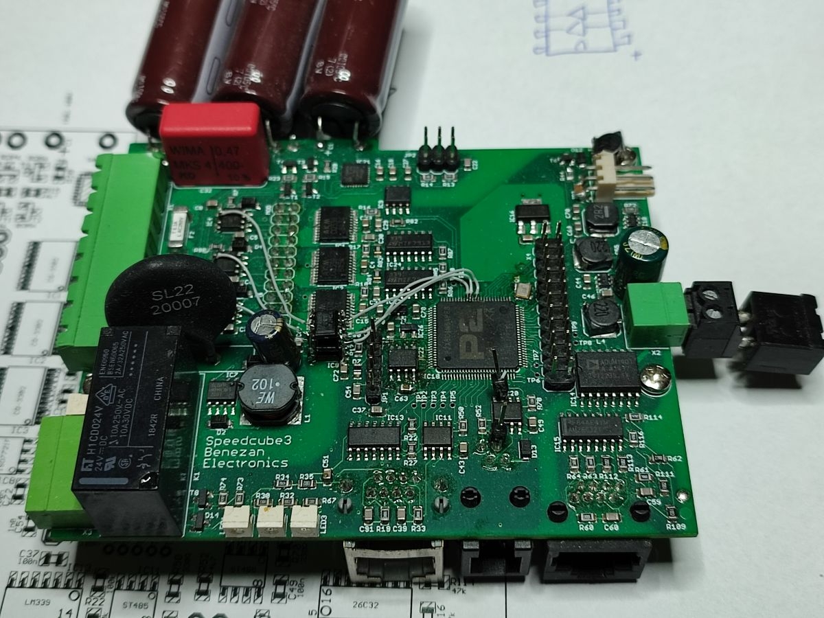
While Chip's board will be surely the most efficient solution I'd prefer my own board for the first experiments because it offers some additional features:
- full protection, hardwired shutdown in the case of overcurrent
- independent current sensors for all three motor windings instead of one common shunt resistor
- bleed resistor switch to dissipate braking energy
- DC bus voltage monitor and temperature sensor
- interfaces for incremental and absolute encoders
- fully isolated, can run on AC voltage up to 250V
So now we're ready. We only need some software... ![]()
Comments
Oh, I love the sight of that board !
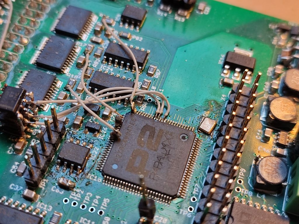
That sandwich - are these two ISO7720FD digital isolators from TI I am seeing there nicely seated one on top of another ?
And you naturally forgot the obvious advantage of that lovely board - you already have it.
And I forgot one important thing:
Two for DC coupled ADC with alternating calibration/sampling cycles to remove the gain and offset error and one for AC coupled conversion. That can be used to get a "zoomed" view of the ripple current. The caps in the picture together with the input resistance of the smart pin ADC in high gain mode forms a high pass filter which lets the ripple pass but blocks DC and fundamental frequency of the motor rotation.
As ErNa mentioned, the low pass filtered average current gives information about torque if and only if the current vector has the right direction relative to the rotor position. But the interesting information how to find out the rotor position is in the ripple current. Amplitude and waveform can be used to detect the position of the "cogs" of the rotor relative to those of the stator. Opposing cogs = small air gap = high inductance = lower ripple, interleaved cogs = wider air gap = low inductance = higher ripple.
Yes. I now use 3 of them to minimize modifications. In the final release 2 (with 2 channels each) should be sufficient, 3 for the PWM signals and one for enable/shutdown.
An additional ISO7721 is used for communication between the P2 and the slave processor in the isolated high voltage section.
I have some first results. I can measure the ripple current of the motor coils with good resolution. But all I get is a long list of numbers. I have to learn the DEBUG features to transform them into something vivid with the scope display feature. But changing between Pnut for debugging and FlexProp for the "real" software development is somehow irritating. It would be really nice if Eric could integrate the debug displays into FlexProp.
Or have the debug as a separate tool
yes, I am bringing that up regulary, put the debug processing into PST and use a newer DELPHI version then currently used, the newer DELPHI versions are platform independent.
Or use FREEPASCAL, could work too.
Mike
I hear you there! My solution so far is printf() to suit CSV spreadsheet importing and make a static graph from a batch.
Yesterday I have done some more experiments. I have moved to the new propeller tool so I can use the graphical DEBUG features. But before I start showing the results I have to explain the theory. The goal of the modifications to the servo board was to find out if it's possible to detect the rotor position without any sensors only by observing the motor current.
This would be easy if the motor ran at some minimum speed. Automatic (sensorless) commutaion can be done by observing the back EMF from the motor. But my motivation was to build a servo drive that has to work also at zero speed while still providing torque. It would be even neccessary to monitor "passive" motion, that is the motor moves due to some external force applied while the power to the driver is shut down (because the protection doors of a CNC machine are open , for example).
The idea is to analyze the ripple current cause by the PWM switching and the motor inductance. This can be done even while the average current is zero meaning torque is also zero. Rotor and stator of the motor consist of punched and stacked sheet iron pieces. The magnetic poles form "cogs" or teeth. When two teeth directly oppose each other the air gap is small and the resulting inductance of the winding around the stator pole should be higher. If the teeth are interleaved the air gap is bigger and the inductance should be lower. Of course, the sum of the inductance of all windings is somewhat balanced out for different rotating angles. Otherwise there would be a lot of "cogging" or detent torque. But if we measure the inductance of individual winding we should see angle dependant changes.
However, air gaps and inductance makes no difference for magnetic south or north poles. So by analyzing inductance it is possible to find out the rotor angle in a range of 0 to 180° but it's not possible to tell if the angle is a certain value or value+180° because the north or south pole of the rotor behave exactly the same. Really exactly? No! The magnetic flux vs. magnetic field curve of iron is non-linear. At low current conditions the flux is far away from saturation but there should be some non-linearity visible in the current waveform, too. If the magnetic field of the winding current has the same direction as that of the permanent magnets in the rotor the flux curve and the inductance should flatten out and the current waveform should become steeper. On the other hand, if the two magnetic fields have opposite direction flux and inductance should increase and the current waveform should bow down a little bit.
The basic idea was presented by ErNa but my approach to the practical implementation is completely different. Instead of measuring the voltage at a shunt resistor in the supply legs of the power stage I had to use isolated current sensors. They are located in the output path of the power stage so I can measure the winding currents at any time even if the current is recirculating (no current draw from the DC bus). To make the best use of the P2 capabilities each current sensor is connected to three propeller pins. Two are used in DC coupled unity gain ADC mode. Two pins are required to allow for simultanous auto-calibration without loosing samples. The third pin is AC coupled and runs in 30X gain mode to get a "zoomed in" view of the ripple current.
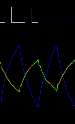
This is what it looks like when I plot the ADC samples of the AC coupled pins directly to a debug window.
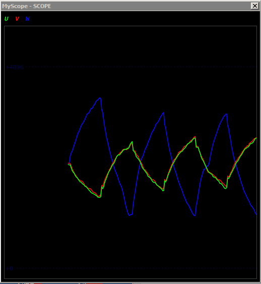
The motor is excited with six pulses with alternating polarity. The duration of each pulse is 45.5µs or 8192 clocks. Each pulse results in a current slope which is sampled 32 times (256 clocks). The visible non-linear bending of the slopes ("shark fin" shape) and the decay of the average towards the center-line is mainly caused by the phase response of the high-pass filter formed by the coupling capacitor and the ADC input resistance. 33nF and 14kOhm result in a corner frequency around 350Hz. The bending of the slopes caused by the filter is symetrical, e.g. upward slopes are bent downward, downward slopes are bent upward. The "art" is to find a little asymetry in the bends.
The "zoom factor" of the scope is quite high. The peak to peak amplitude of the ripple current is around 0.6A what translates to 60mVpp at the ADC pin. Full scale (12 bits = 0..4095) in 30x mode should be around 160mV. There is surprisingly little high frequency noise but there are some artefacts in the waveforms like peaks or kinks around the switching points. I think they are caused by reflections of switching noise in the motor cable. The peaks are still there when I disconnect the motor and curent should be theoretically equal zero.
Is it, that we see three currents adding up to zero?
Yes, that's Kirchhoffs law. The sum of all currents to a star point is zero (as long as there is no leakage). Of course, we have to consider that the curent sensors are imperfect and have offset and gain errors. So the sum is not exactly zero. The RC time constants of the filters also might not match exactly, so there's an additional shift.
What I did next is trying to calculate some values that are proportinal to the peak-to-peak amlitude and the asymetry of the curve bends and are as robust against noise as possible. Here is my strategy:
(A+C)/2 is the (nominal) center point and B the actual point on the middle section of the curve. The (absolute value of the) slope value should be a measure for the amplitude which is inversly proportinal to the inductance. The bulge value should be a measure for the non-linearity and its direction (signed). To cancel out any offset errors and effects of the RC filtering the differences or sums of two consecutive pulse periods have to be used.
It just came to my mind that the above calculations could also be carried out by the Goertzel unit.
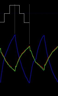
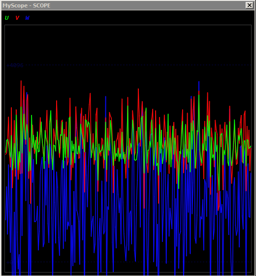
The white traces are the coefficient table contents for the weighted accumulation. The 1st one perfoms the C-A operation and the difference between odd and even pulses (up/down slope). The 2nd one performs the B - (A+C)/2 operation and summing of odd/even cycles. The square waves could be replaced by sine waves of the fundamental frequency and 2nd overtone which could give smoother results.
Unfortunatelly, there is only one Goertzel unit per cog so simultanously analyzing of three phase currents would "waste" two cogs. However, as the P2 has fast multiplication I don't see a problem doing the equivalent in software in only one cog.
When I plot the absolute value of the ripple amplitude and turn the motor with the fingers I can actually see some variations.
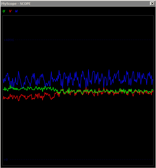
This is not the waveform of the current but the result of the "slope" calculations recorded once every 10ms. So the whole plot covers ~2.5s and the change happens around 1s at the U and V traces. It looks somewhat noisy but I'm optimistic that with some filtering useful information about the rotor angle can be extracted.
The bad news is that the result of the "bulge" calculations is totally lost in the noise.
Before spending more time on debugging or improvements I'd like to do a simulation to find out how large the theoretical signal is to be expected and if there is a chance at all to measure anything useful. Does anybody know how high the magnetic flux is in a brushless motor? I know that rare earth magnets can have something like 1.2Tesla but the iron core of the stator has a different cross section and the air gap weakens the field. Together with a magnetisation curve of iron we could simulate how the ideal signals should look like.
There is no chance to simulate something as all motors behave differently and some show no signals at all. Even if you can not see any dimensional difference. It looks like burried magnets are more problematic, but that is just in average. The information I derived from current measurements are all measured in real time from a single shunt, that is, I have an R-C-type IRF with a variable time constant that I adjust to actual speed to avoid phase shift due to the time constant of the filter.

Such beautiful signals can be derived:
A simulation would be the "best case" without any gain or offset errors and without noise. I don't claim that this would reflect the reality or is of any practical use except for the following: If the simulation shows that the signal to expect is far below of the threshold my real hardware can measure then I know I'm on a dead end road. So I'd use it only for the verification or falsification wether my circuit has a chance to work at all. If there is one I spend more time for improving it. If not I save wasted time.
And yes, it's beautiful.") But without any formulas how the dots are calculated it's nothing but abstract art.
But without any formulas how the dots are calculated it's nothing but abstract art.
And yes, I know that there are motors which have a solid drum of neodymium as rotor. Those don't show any variance of inductance because the rotor has no teeth. However, the non-linearity of the magnetic flux curve should still be measurable as long as the magnetic field is strong enough that the curved part of the hysteresis diagram is reached. Or in other words, if the diagram looks like this
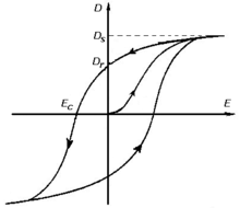
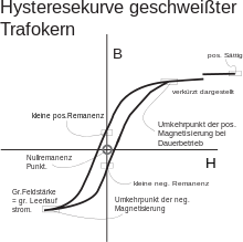
we won't have problems. But if it looks like this
and the magnets aren't strong enough so the the set point remains in the linear region near the center then it will be hard to get a usable signal.
Another reason why simulation can be useful even if it's non-realistic when it comes to errors is: It's good for debugging. If the simulated curves look like the ones I'm expecting then I know I'm on the right path. If not then either my formulas or code is wrong or the whole design is based on false assumptions.
If something doesn't work then it's a bad idea to try to re-adjust parameters if there are many of them. If you tune the wrong paramater nothing will change.
It's much better to start with an ideal system that is known to work and then replace the known-good parts with the real (imperfect) ones step by step. The moment the whole system starts to fail you have identified the problem. This remains true even if you don't understand every detail of the whole system.
I was curious if you have been successful with driving a BLDC with your setup.
Any real loading on the motor to try an maintain speed? One of the obstacles we have encountered is that everything works great on a bench with a "balanced" motor, but for our particular application the motor is not at all balanced. Which means that the controller has to fight going up hill and then coast going down hill on every rotation.
The epiphany I had was when reverse engineering another controller for our motor. See Video ( http://www.kit-start.com/Parallax/20210611_184204.mp4 )
notice that ALL three phases are producing relatively the same pulse, and when the motor is stopped, all three phases are perfectly aligned and still driven HIGH and LOW at 20kHz.
THIS effectively shorts all three windings of the motor together as an electrical brake. If you try to turn the motor by hand in any direction the phases will dynamically oppose your efforts so that the motor shaft remains locked. As the motor moves on it's own the SINE relationship is between phases and skews one way or the other depending on which direction the motor is turning. The MORE deviation there is in the sine wave the more current the motor is driven with.
You won't find a pattern like this with Google, at least I didn't at first until I realized what I have on the scope is an extreme closeup of the typical 3-phase Sine wave I was finding on Google. If you average the square waves and treat it as an ordinary PWM .... THEN you have the typical 3-Phase Sine relation. Sort of.... Holding the motor in position, ALL three sine waves would be aligned. it's only during rotation or trying to dynamically counter spin the motor that the 3-Phase sine waves migrate into their typical 120 deg separation.
So.... the "golden code" would be able to transition from 3-Phases Aligned to 3-Phases 120 Deg apart in either direction seamlessly.
I just wanted to share, I didn't want to step on any toes or hijack the thread.
I am also very curios what Chip has come up with in the way of a BLDC board he was working on.
Let me point: if you apply the same voltage to all terminals, whatever the voltage is related to „ground“ the motor sees zero volt applied. And all terminals are just connected. The moment you rotate the rotor incrementally an incremental voltage will be generated in the windings that creates a current rise due the inductance of the windings and this current will create a counter torque to the driving external torque. The energy externally supplied is stored as current in the inductance. If there is no resistance. Else (in a real motor) the energy is dissipated.
If you apply a pwm-ed „Zero“ voltage, at any moment the windings see a voltage and there will be a current slope (ripple) that allows to determine the rotor position and so to apply a voltage of given amplitude and phase and such make motor control an easy task. Believe it now or know it later😊