How do you intepret this _CLR MODCZ Operand cccc or zzzz = 0000. C/Z = 0
in Propeller 2
What is cccc or zzzz ? The instruction has 2bits for flag "z" and " c" and 1 bit for "I" imediate instruction operation . EEEE 0000000 CZI DDDDDDDDD SSSSSSSSS is the syntax . Condition instruction flags destination and source. What does MODZ operand mean? Is there some document for PASM Instruction spread sheet.
Regards and Thanks
Bob (WRD)


Comments
From the instructions_v32.txt:
So cccc and zzzz are the 4 bits that the constants define. They will be put into the D and S field.
Internally this modify instruction is just a bit-lookuptable, where C,Z is a 2bit index (= 4 values) and the result ist taken from the indexed cccc / zzzz bit.
Andy
Thanks for response. Is it possible you have a couple example instructions using these constants?
Regards and Thanks
Bob (WRD)
Andy
Just noticed there was more in the post didn't scroll it . Ignor the question
Sorry
Regard and Thanks
Bob (WRD)
Andy
I looked through what was posted. It would be of help if you give an example how the MODCZ operand works in some code.
Regards and Thanks
Bob (WRD)
I've used it to preset the flags in the past.
Here's one where the called routine writes its result only if the C flag is set. It allowed an additional priming feature to be added without adding any new instructions to the called routine. This meant the more taxing execution flow elsewhere wasn't impacted - It used this:
call samplersetc wc. Register/variable samplersetc had bit31 set to always set C.... modc 0 wc ' clear C flag call #sampler ...EDIT: A tad complicated, rereading that.
The instruction is very universal, but therefore also a bit complex. Like in the LUTs of an FPGA, you define in a truth table the resulting bit for any combination of C and Z.
Say you want to set Z to the state of C, then the truth table looks like that:
 C  Z | zzzz
------|-----
 0  0 | 0
 0  1 | 0
 1  0 | 1
 1  1 | 1
        '-> %1100 = zzzz
when C is 1 the result is 1, if C is 0 the result is 0
so you can write the MODx instruction like that:
MODZ %1100 WZ 'sets Z to Cbut it is easier to understand with the constant:
MODZ _C WZ 'the same with the named constantMODCZ lets you affect the C and the Z flag in one instruction, you can for example swap the two flags:
 MODCZ _Z, _C  WCZ       'swap c and Z
        |   |
        v   v
        C   Z
hope this helps.
Andy
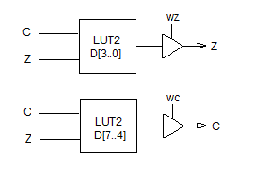
The MODCZ as a blockdiagram:

The MODC and MODZ are just alias instructions to simplify the use , if you need to modify only one flag.
MODCZ/MODC/MODZ is a "D-only" instruction, where D[7:4] = cccc and D[3:0] = zzzz.
S field is fixed and part of the opcode.
Thanks, TonyB
I have edited the picture above.
Ariba
It looks like the block diagram will determine what the 4 bit instruction code will do in the MODCZ can you post the block diagram here.
MODCZ c,z {WC/WZ/WCZ} Math and Logic EEEE 1101011 CZ1 0cccczzzz 001101111
MODC c {WC} Math and Logic EEEE 1101011 C01 0cccc0000 001101111
MODZ z {WZ} Math and Logic EEEE 1101011 0Z1 00000zzzz 001101111
Not sure about MODC and MODZ being an alias with the same block diagram wouldn't they be modified to reflect C01 and 0Z1 masking?
Thanks and Regards
Bob (WRD)
The block diagram is always the same. You can replace D[3..0] by zzzz and D[7..4] by cccc, to match the bit names in the instruction encoding.
You can see this LUTs as a 1bit wide ROM with 2 address inputs = 4 bits total. This address inputs are connected to the current state of C and Z. Depending on the state of C and Z one of 4 bits in the ROM is read and defines the new state of the C or Z flag, if the WC and/or WZ effect is set.
From the instruction encoding, you posted it's obvious that all 3 instructions are the same. Unused bits are just set to zero for MODC and MODZ. You can also affect only C or Z with MODCZ, but then the assembly syntax requires a dummy argument for the not used flag.
Andy