

Relative (precision) counting
 Circuitsoft
Posts: 1,166
Circuitsoft
Posts: 1,166
in Propeller 2
Having looked at the counting smartpin modes, and the reciprocal counting demo, I'm wondering if there's a way to count against an external reference clock instead of against sysclock.
How I do this with other counting equipment is by having one counter set with an output pin, connected to the gate on another counter.
Is this possible with smartpins?
Comments
Is smart pin mode %01100 (P_REG_UP) what you're looking for?
That would be half of it. Is there an output mode, where you count on A rise, and B is high when count is > x and < y?
I doubt it -- that seems a bit specific for a general operation of a smart pin. Still, PASM2 is pretty easy to use, even for those of us who are not regular assembly programmers.
As above, there are gated modes, but if you are after precision you will likely be better to count both frequencies and ratio them in maths. I'm sure that's how the counter I have here, does ChA/ChB frequency ratio.
With any gated mode, you need to take care about the gate time, as that limits the capture time and thus the precision. You also lose information when the gate is off.
With the reciprocal modes, capture is continuous so no edge information is lost, and the hardware auto-rounds time to the neatest whole period, so the precision limit is the SysCLK of the P2.
Because no information is lost, you can total multiple readings and use that to get a second, slower but higher precision, reading rate.
For extreme precision cases, I have seen Exclusive or gates + LPF used to mix two close frequencies, one of which is Atomic quality, and then the difference frequency gives you a magnified error.
eg beating 1MHz and 1.001MHz signals gives 1kHz error, and then 1ppm reading of that 1kHz gives 1ppb equivalent difference error.
Yes ... but more precision in the question is needed.
There is three counting groups in the smartpin modes:
I think when you talk about counting "against sysclock" ticks you are likely meaning modes that accumulate time when gated with an input. Or maybe it's a combo like the reciprocal counting demo. Chip used all three count mode types, one in each smartpin.
An example: The PDM bitstream of a Sigma-Delta ADC is handled by using the bitstream as the gate control of a time accumulator. And that's the common industry solution in dedicated ADC designs, btw. So not just a makeshift hack.
PS: There is merging of these modes. Count and Accumulate cross where the clock is an input for example. So when the PDM bitstream has an external clock source alongside then that becomes a gated Count mode. The distinction becomes vague.
In my case, I have a 10MHz reference from a gpsdo, and another frequency I want to measure. It might be 32MHz, or it might be 32768Hz. Either way, I'd like 100ppb precision in one second.
The biggest reason not to feed the gpsdo signal directly to xin on the p2 is that the signal level could very well be too low to properly pick up. Also, I'd like to use as much off the shelf circuitry as possible, and the p2 demo board does almost everything else I need without any extra hardware.
Googles GPSDO ... GPS disciplined oscillator. :shrug: I have no experience. JMG has guessed you are wanting to measure the ratio of the two input frequencies. Is that the case? The XOR input option JMG mentioned also exists in the Prop2.
EDIT: Err, the XOR is clocked at sysclock so probably not suitable.
Jonny Mac did give the right mode, just that Chip's choice of naming is deceptive. P_REG_UP uses two inputs. Here's my constant description from way back:
SPM_CNT_UP_ENA = %01100_0 ' count: A clock up, B enableAt 100ppb you would not really need to do that, but as a reference point I've tested clipped sine oscillators into P2, and 26MHz was fine, and 38.4MHz was around what I'd call the corner.
A 10MHz clipped sine source would be fine.
The newer P2edge board has a TXCO and a dual inverter buffer
The simplest approach on existing HW is to run two reciprocal counters, with the same nominal timebase.
The one connected to your 10MHz GPSDO calibrates the crystal, to get a ppm correction value, and then the other counter measures your 32kHz~32Mhz.
If you do not need continual reading, just (re) arming the two counters at the same time would be good enough.
10MHz will be within 100ns of 1 second, and 32kHz will be at most ~30us over 1 second.
If you wanted continual reading, one thing to watch could be snap-creep effects, because the reciprocal capture rounds up time to the next whole Fin period, two counters are not going to stay time-phase locked over long times.
Ideally, you want the short term (sub 1 second drift) of the xtal to be caught the same way, by both reciprocal counters.
To improve that, I would capture say 10~100 times a second, and then sum those captures with the most overlap. if you capture 100 times, the worst window skew is 1/100th of 1 second
P2 can easily manage 100ppb/second, that's 10MHz SysCLK, with 100MHz you can do 10ppb/second and 200MHz is 5ppb/second
On a related topic, of 10MHz GPSDO input, a standard 10MHz reference is a sine wave, ~1vP-P. One way I've found that seems reasonable to turn this into a square wave is a schmitt trigger inverter feeding back on itself to a capacitor. By making an "oscillator" about 7MHz, it takes very little signal level (lots of potential attenuation) driven into the cap to pull solidly to 10MHz.
If I wanted to do this on a Propeller 2 I/O pin, using the Schmitt Trigger Inverted local feedback mode, where should I expect the high/low trigger points to be to calculate the capacitor to use?
Sample: https://falstad.com/circuit/circuitjs.html?ctz=CQAgjCAMB0l3BWK0DMB2AnCgbNtAODAFm3xTDTWxAUhproQFMBaMMAKACUaiiQUkfkQzVB-OhDDxJUOTAQcK-BHxBE4NKgKHhw8ZACYih7DPPx+XJgGcAljYAuAQwB2AYyYcA5r2GbVYTBqOkgOdxBsYwEEQ0i0OJRYuQRobFYMEDY0sENDBARsBDATEzz8ZDhOMDJ4xN00HB0JZCQIQ1QBTrCAdzqYuLx6iQ4AJ36kuMaxZMlaOA4+6YGQZfEoRa0ZwejJjYB7EAqIOg0MTJhyfMq4FAxIKKQ6OIqUDkO0PVPIc-oYeDuD2uz1WAg4QA
Hmm, running that close to the limits, could be quite prone to jitter and noise ?
See this post
https://forums.parallax.com/discussion/comment/1520409/#Comment_1520409
which mentions 1v p-p for schmitt self oscillation. It maybe be better to not use the schmitt at all, and rely on the slew rate being enough ?
That 1V p-p window is a bit too high for clipped sine specs, but a 74AUP04 series part has lower schmitt action pins, of ~ 250mV Hyst, (not 74AUP14) so they could use used,
or you can use 2 gates from unbuffered 74AUP2GU04 to provide enough gain to give 3v3 drive.
That's what is used on the the Edge board, to buffer the TCXO. Or, you could use a PL133-xx from Microchip, which saves the R & C for a reduced BOM, for a bit higher price.
There is Prop2 in-built options for schmitt and inverter feedback and also that 15k resistor. I suspect you know that though. So I guess you're asking what is the Schmitt levels of Prop2 inputs, right? I vaguely remember 1.0 volt span, so 1.15 V to 2.15 V ...
First test nabs me 1.1 V to 2.1 V.
Lol, that previous post was even this year.
Here's the pin mode
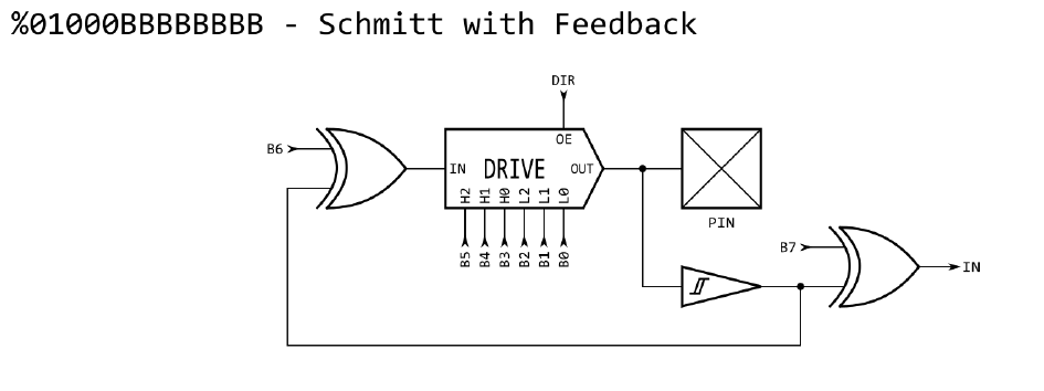
P_SCHMITT_A_FB | P_INVERT_OUTPUT | P_HIGH_15K | P_LOW_15Kand mode diagram from docs: (B6 is set for output inversion and P_HIGH_15K | P_LOW_15K config B[5:0])Another approach, for 10MHz sine-signal drive, which would allow the Schmitt to be enabled, is to add a series inductor, so that the RLC circuit is broadly resonant at 10MHz.
Depends on the PCB+Pin capacitance of P2, but a starting point for 10MHz could be 33uH~39uH inductor and 100pF~1nF NPO in series to the pin.
That should 'amplify' to swing rail-rail at P2, when driven from a typical clipped sine output.
Another idea just occurred to me: could I use the non-schmitt-trigger negative feedback mode (maybe clocked feedback?) with the unanimous input filters to clean up the edges?
Is SysCLK was high enough, sure. It cannot do any harm")
Clocked feedback you would need to try, as the quantize nature of that would not give precise slicing, and so it would delta-modulate the average so it was 50%.
If the main SysCLK and the precision reference were nearly phase locked, that could introduce a jitter-modulation effect you did not want ?
I would probably be doing this on the demo board, so the 20MHz crystal PLLd to 180MHz. Hopefully that should introduce enough phase noise to reduce the jitter effect you're talking about?
Reiterating for the sake of all info in one place:
The precision reference is 10MHz sine (not clipped) and anywhere from 1Vp-p to 1.5Vrms.
Measured clocks are logic signals, generally 3.3v, sometimes 1.8v, and either 16384/32768Hz (reciprocal mode) or 16-40MHz (either mode, direct might be more precise).