ESP8266 + P2 - my project for "simple" CM2302 Temp/Humidity Transmit
 Ken Gracey
Posts: 7,419
Hello,
I'm looking for some people to join me on a project.
At the P2 Live Forum I mentioned that I'd like to take on a project to document a basic IoT effort with the ESP8266 and the P2. My programming skills are low, spread across P1/Spin, P1/BlocklyProp, BASIC Stamp, micro:bit/micropython, and my main fit at Parallax isn't this kind of thing. I have until June 21st to make a working project, and then I have to shift over to some educational conference presentations and our internal end-of-year/inventory processes. That'll keep me booked until mid-July, along with the P2 Live Forums. It's likely I've bitten off far more than I can chew in this small time. Aside from running code examples in the Quick Bytes and from forums, this would be my first P2 project.
I'm trying to start with what might be the most basic setup: sending the temperature to a remote location and showing it on PST (or an LCD). The project looks like this:
CM2302 Temp/Humidity Sensor to P2 Edge to ESP8266 ))))
WiFi Access Point to www.cloudmqtt.com to WiFI Access Point
(((( ESP8266 to P2 Edge to Parallax Serial Terminal (and show the temp/humidity)
I'm working off of the article Jon Titus created as a starting point https://www.nutsvolts.com/magazine/article/for-iot-projects-call-json but would like to do this without the ESP8266 microcontroller (and use its WiFi capability). I created a CloudMQTT account.
The ESP8266 module I'm using is https://www.amazon.com/gp/product/B08FZ9YDGS/
These projects appear entirely simple with Arduino; you can even configure the ESP8266 with the Arduino IDE. The P2 needs similar examples with the same ease of use. The goal is to develop a few examples with the P2 and document them as P2 Quick Bytes. First -- start simply as shown in this example, but work towards an example that truly shows what the P2 is capable of doing with mechatronics once we work out the basics.
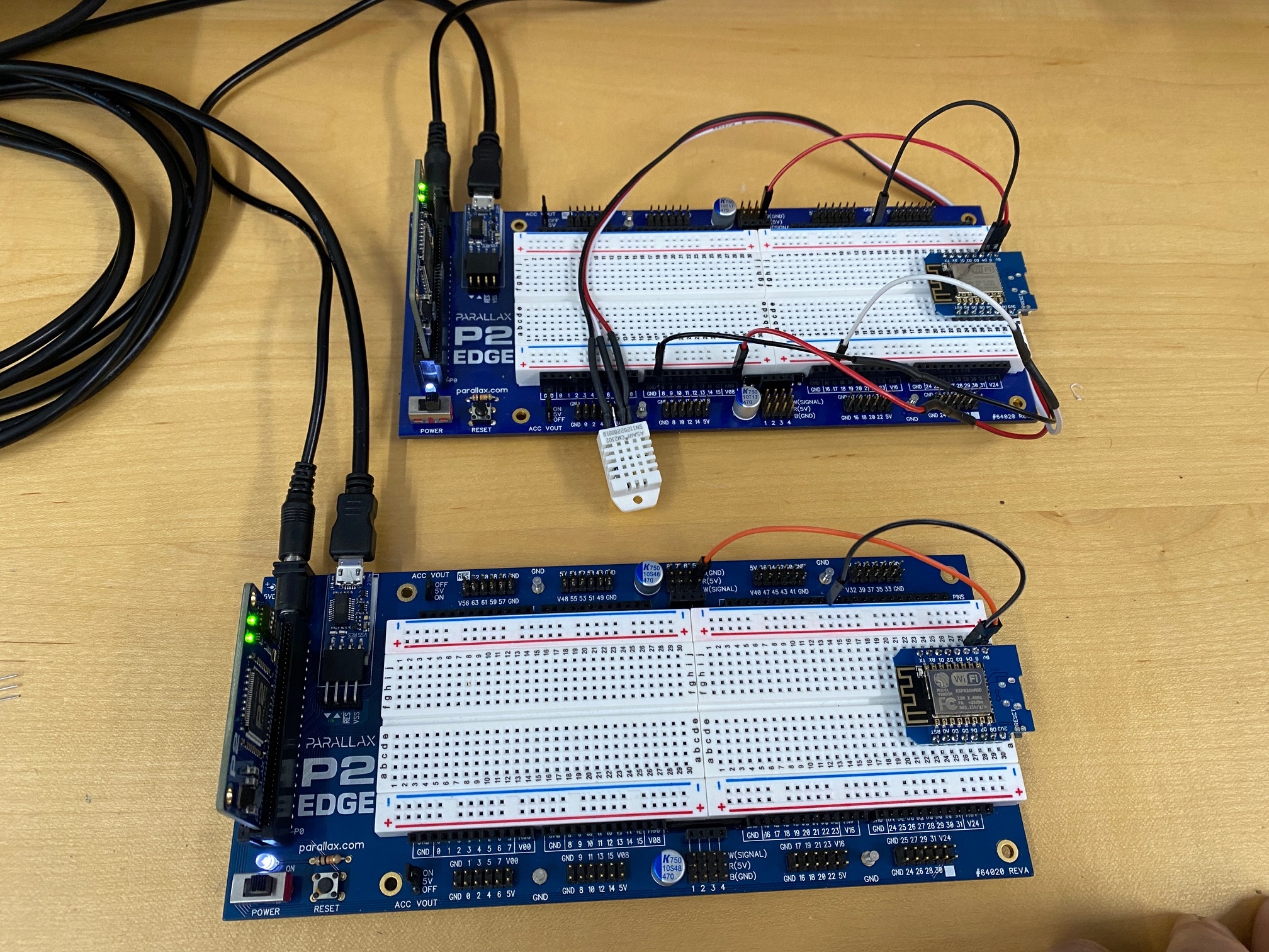
At this point, I've only set up two P2 Edge with JonnyMacs and got the first part working: CM2302 temperature display via PST. I have the CloudMQTT account and the user, password, port, SSL port, websockets information. I believe the next step is that I learn how to configure the ESP8266 module have WAP access and receive serial commands from the P2. Seem about right?
Who is interested in following along, or joining me on this project?
Ken Gracey


Comments
I ordered those ESP8266 modules. Using the ESP as a WiFi bridge for the Propeller is something I've wanted to do for a while.
Is there the firmware of the Parallax WX ESP8266 WiFi Module on the ESPs? Or do you plan to use it “bare bones”? I’m using ESPs with micropython, and am in the process of creating a minimal web interface for configuration of WIFI networks etc. And it’s supposed to produce MQTT. The P2 could deliver the Sensor data via uart. Currently the ESP does it itself via I2C.
Am I missing something?
First why not use the parallax module? I think its better.
The firmware parallax developed for it will work on other modules like yours,
it may not allow a wifi firmware upgrade though, unless you upgrade the flash.
The parallax module has a 16mb flash, not 4.
This allows you to do OTA over the air firmware upgrades.
I myself have worked with it lots, i created a thread dedicated to it, and its firmware compilation.
https://forums.parallax.com/discussion/169250/parallaxwx-esp8266-raspberrypi-debian-esp-open-sdk-simpleide-openspin-proploader-devel#latest
Then I created a model railroad controller using a PAB and 2 wx esp8266 modules in the engine, and one in the caboose.
The engine calls the caboose using one of the wifi modules to report if its still moving (for derailments and lost cars, plus an eot blinker using a prop.
The commands to setup a http connection is actually very simple, you tell it how many bytes, and the receiver also needs to know that.
The other esp module in the engine is used for a webpage control interface for the user.
This page shows feedback from the engine that refreshes every 2 seconds using java script.
And any webpage change is sent after the change is made.
I did all this in spin, there are also C examples in the simple ide library under wifi i think, thats actually how I learned how the modules firmware works.
Since you spin, just read my chicken scratch code at the end, to get an idea on how to have a prop communicate with a webpage that is hosted on that same esp. I imagine you can convert p1 code to p2.
https://forums.parallax.com/discussion/comment/1506197/#Comment_1506197
The model railroad controller project has all the webpage html, css files, firmware, code, etc.
The http connection prop - esp - esp - prop... is pretty much one way data, which is what you are doing.
It can go the other way too, you just need to do the same on the other prop,... ping/pong
The commands are serial, and in the modules manual!
The parallax esp device has RTS and CTS wired to the dip interface, and the parallax esp firmware allows you to select which one you want for your prop reset.
Tons of work was put into the PARALLAX ESP MODULE. WTF BRO!
If you didn't know about all this, then dang, you've been missing out on this fantastic module and its firmware!
If you are MQTT or bust, then the first step is, what is the mqtt packet format?
Is it any similar to a http request? https://developer.mozilla.org/en-US/docs/Web/HTTP/Messages
If I had 3 days to do it, I would just put the esp module behind a router that has port forwarding, port 80 to the module. You can delete the module html pages after you configure it, and just leave your custom html page, and even do some crude password in html/javascript if you want basic protection.
If its just local wifi router range for both esp's, you don't need any internet or protection to make prop<->esp<->localrouter<->esp<->prop work.
This webpage is hosted and served from the esp. The pwm/caboose data is requested by the webpage using javascript from the esp firmware, which when asks the prop for that data.
https://forums.parallax.com/discussion/download/135096/Engine.jpg
https://forums.parallax.com/discussion/comment/1521627/#Comment_1521627
I also provide a putty connection to serve as a diagnostic, which could also be used as a readout, and even port forwarded to the net, (port 23). But that exposes the programming interface also to the net.
Putty can do ANSI commands, so I use those in all my projects, putty, with ansi commands, allows basic formatting, positioning, direct connection to the module ip using putty telnet connection.
We will use the Parallax WX Module. I initially thought a bare-bones approach would be best, but the post from @"Clock Loop" and @deets gave me the reason I needed to reconsider. Initially, I thought for production customers it would be best to go bare-bones, but the goal of completion is made much faster with the Parallax module. Clearly, the Clock Loop example and our own tutorials would be a good start.
Now, I'm facing delays in getting started and it'll be early July before I can return to this project (stuff to do at Parallax).
Ken Gracey
Several years ago a built and out door weather station using the P1 and a XBee WiFi module. Link hereWeather Station.
Since then I have made some changes and added another station using an ESP8266 WX module after adding UDP to this module which is needed to send the JSON data from the weather station to an inhouse Web Sever.
The original Xbee unit was used because it allowed for putting the unit to sleep and then later wake up and make a connection and inform the P1 to send the data. The intent was to use a battery to power the weather station but it turned out no battery could handle the station for several months of operation.
The current configuration is using a BME280, ESP8266 WX module, AS5048A for wind direction and a magnet and HALL fet for wind speed.
The P1 has more than enough power to handle this project and using a P2 would be over kill.
While all the pieces work as designed the data output is not that good. The plastic heats up and skews the temperature readings and calibrating the wind speed is hard to due.
Here is a link to the weather data that has a timer added to inform me when the weather station locks up which does not happen to often.
Weather Station 1.
Weather Station 2
Mike
I don't think this kind of project is about power. The ESP has >100MHz, also way above what would be needed for a weather-station. And in general we (thankfully) live in times of abundant CPU power, even in these microcontrollers. PiCo has a cortex M-something with 240MHz, twice as much as my first PC. Let alone my AMIGA500, which was half of what even the puniest of my Arduinos pulls. So in most cases we have more power than we need, and unless that comes with egregious power consumption, that's fine.
These kinds of projects are (besides Ken learning something) illustrations of the nature of projects one can accomplish with P2. The wider the gamut of examples, the more attractive.
I would like to mention to everyone who uses a esp module which is soldered smt to a carrier board, like parallx's WX esp8266 module.
The one parallax uses is soldered to a carrier board.
When this is solder pasted, and then "cooked" most of the solder looks ok, but it is not always.
I have ordered over 10 of the sip or dip modules from parallax, and have noticed one major issue that has appeared a few times now.
Simply put the ground for the module isn't bonded well or possibly cold joint, when I get a new module and it has issues staying connected, issues taking programs,...
I fire up a fine tipped solder gun and some fine solder, and give each smt pin a touchup. You can tell when you hit the ground it takes a long while to heat up, even with a nice precision gun, and you will see why its probably the issue.
It might be wise to get someone to touch up the ground smt pad on those production modules!
I am very interested in both a good tcp/ip solution, and MQTT running on the Parallax. I sometimes teach MQTT classes. It would be great to be able to do that with the P2.